Operating Instructions Model 100E Instruction Manual
86 045150102 Rev XB1
6.7.6. Electrical Test
The electrical test function creates a current, which substitutes the PMT signal, and feeds
it into the preamplifier board. This signal is generated by circuitry on the pre-amplifier
board itself and tests the filtering and amplification functions of that assembly along with
the A/D converter on the motherboard. It does not test the PMT itself. The electrical test
should produce a PMT signal of about 2000 ±1000 mV.
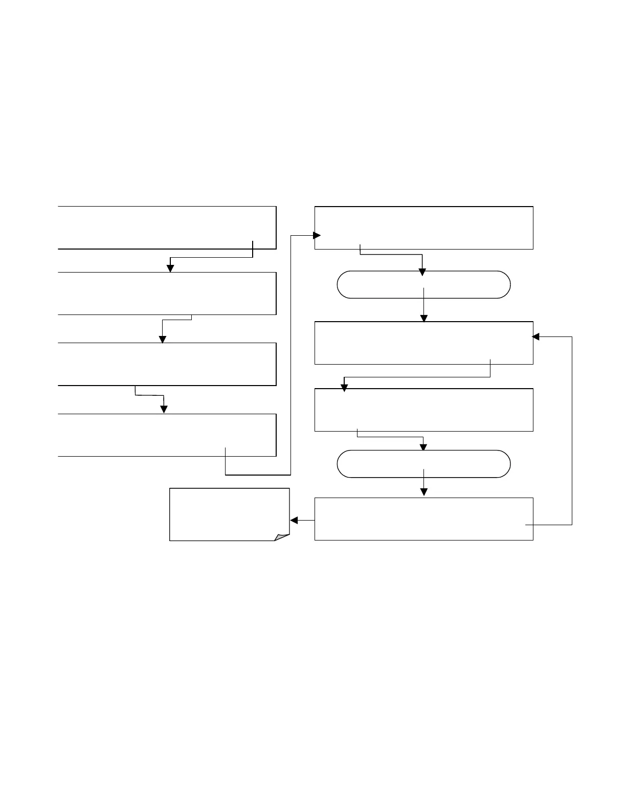
To activate the electrical test press the following keys.
SAMPLE* RANGE = 500.000 PPB SO2 =X.XXX
< TST TST > CAL
SETUP
SETUP X.X
PRIMARY SETUP MENU
CFG DAS RNGE PASS CLK
MORE
EXIT
SETUP X.X
SECONDARY SETUP MENU
COMM VARS
DIAG
EXIT
DIAG
SIGNAL I / O
PREV
NEXT
JUMP
ENTR
EXIT
DIAG ELEC
RANGE = 500.000 PPB O2=X.XXX
<TST TST>
EXIT
SETUP X.X ENTER DIAG PASS: 818
8 1 8
ENTR
EXIT
Press
NEXT
until…
DIAG
ELECTRICAL TEST
PREV NEXT
ENTR
EXIT
Press
TST
until…
DIAG ELEC
PMT = 1732 MV
SO2=X.XXX
<TST TST>
EXIT
While the electrical test is
activated,
PMT
should equal:
2000 mV ± 1000 mV
6.7.7. Lamp Calibration
An important factor in accurately determining SO
2
concentration is the amount of UV
light available to transform the SO
2
into SO
2
* (see Section 10.1.1). The model 100E
compensates for variations in the intensity of the available UV light by adjusting the SO
2
concentration calculation using a ratio (LAMP RATIO)that results from dividing the
current UV lamp (UV LAMP) intensity by a value stored in the CPU’s memory
(LAMP_CAL). Both LAMP Ration and UV Lamp are test functions viewable from the
instruments front panel.