4: INSTALLATION
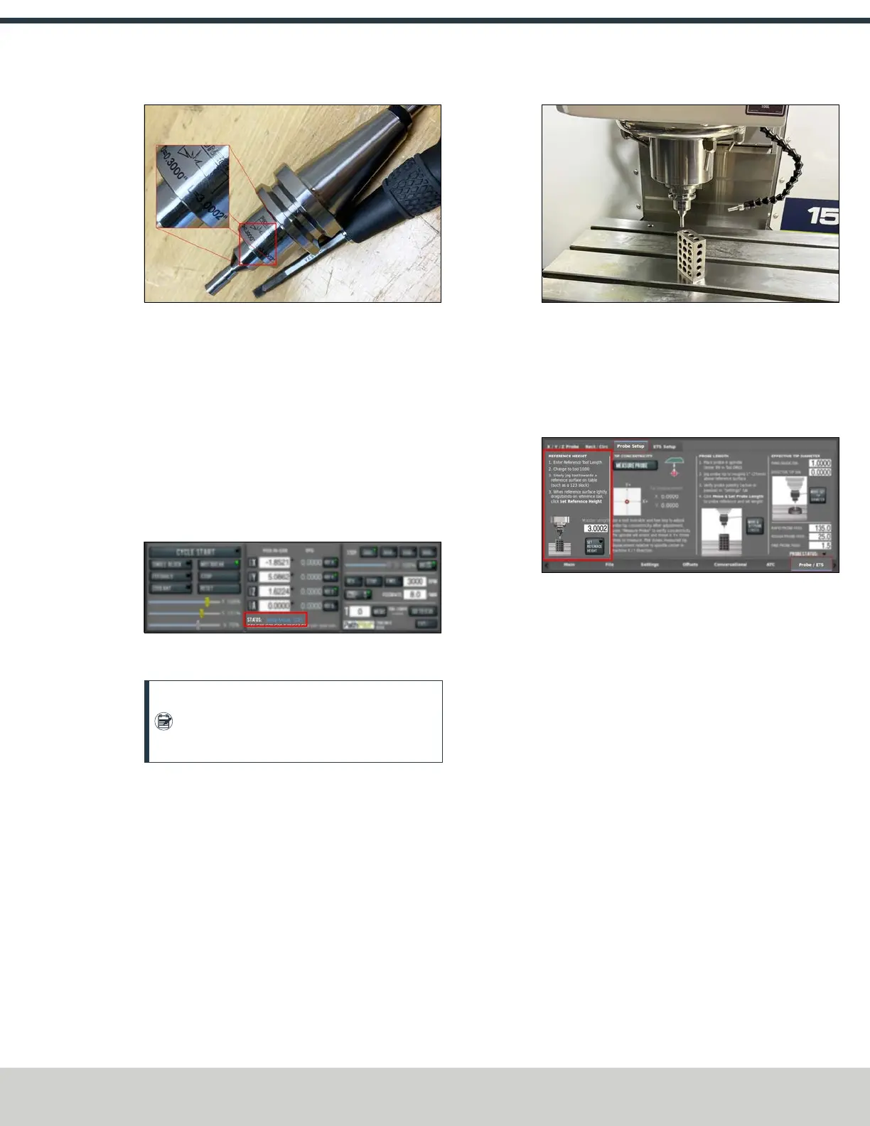
Figure 4-229: Diameter and length measurements
engraved on to the calibration tool.
2. From the PathPilot interface, on the Offsets tab, enter
the diameter and length for the calibration tool into tool
1000.
3. Wipe off the machine table.
4. Put a 1-2-3 block on the machine table.
5. Verify that the machine is in setup mode. Use the key on
the top of the operator console to switch between
modes. For more information, go to "Operating Modes
Reference" (page25).
Figure 4-230: PathPilot indication of which mode the
machine is set to.
Note: In setup mode, you don't need to press
the hold-to-run button to jog the machine with
the enclosure doors open.
6. Jog the table until the block is under the calibration tool.
Slowly jog the Z-axis down until it's tip drags on the 1-2-
3 block.
Figure 4-231: Calibration tool near the top of the 1-2-3
block.
7. Close the enclosure door.
8. From the PathPilot interface, change to T1000.
9. From the Probe/ETS tab, on the Probe Setup tab, select
Set Reference Height.
Figure 4-232: Reference height section of the probe
setup.
10. Remove the calibration tool and load the probe into the
spindle.
11. From the PathPilot interface, change to T99. Make sure
the probe LED turns green. While watching the LED, flick
the probe tip to make sure that the probe responds.
©Tormach® 2024
Specifications subject to change without notice.
Page 101 UM10811: 1500MX Operator's Manual (Version 0424A)
For the most recent version, see tormach.com/support
 Loading...


