9. Manually jog the A-axis to align the reference mark on
the casting within the bracket on the reference label.
Once aligned, from the PathPilot interface, select
Reference A-Axis.
Figure 4-218: microARC aligned to the Zero label.
4.8.6 Install the Probe and Tool Setter
Complete the following steps in the order listed:
Before You Begin 98
Required Tools 98
Notes 98
Wireless Receiver Installation 98
Wireless Probe Installation and Setup 99
Adjust Probe Tip Concentricity 100
Set Probe Length and Diameter 100
Probe Status Lights Reference 102
Tool Setter Installation and Setup 102
Align the Tool Setter's Stylus 103
Reference the Tool Setter 104
Set G37 Position 104
Before You Begin
Make sure that:
l The machine is powered on.
l The enclosure is installed.
Required Tools
l 1-2-3 block
l Metric hex wrench set
l Dial test indicator (0.0005 in. indicator or better) with
magnetic base
l Flat-blade screwdriver
Notes
l Torque fasteners to the noted specification. If no
specification is noted, hand tight is sufficient.
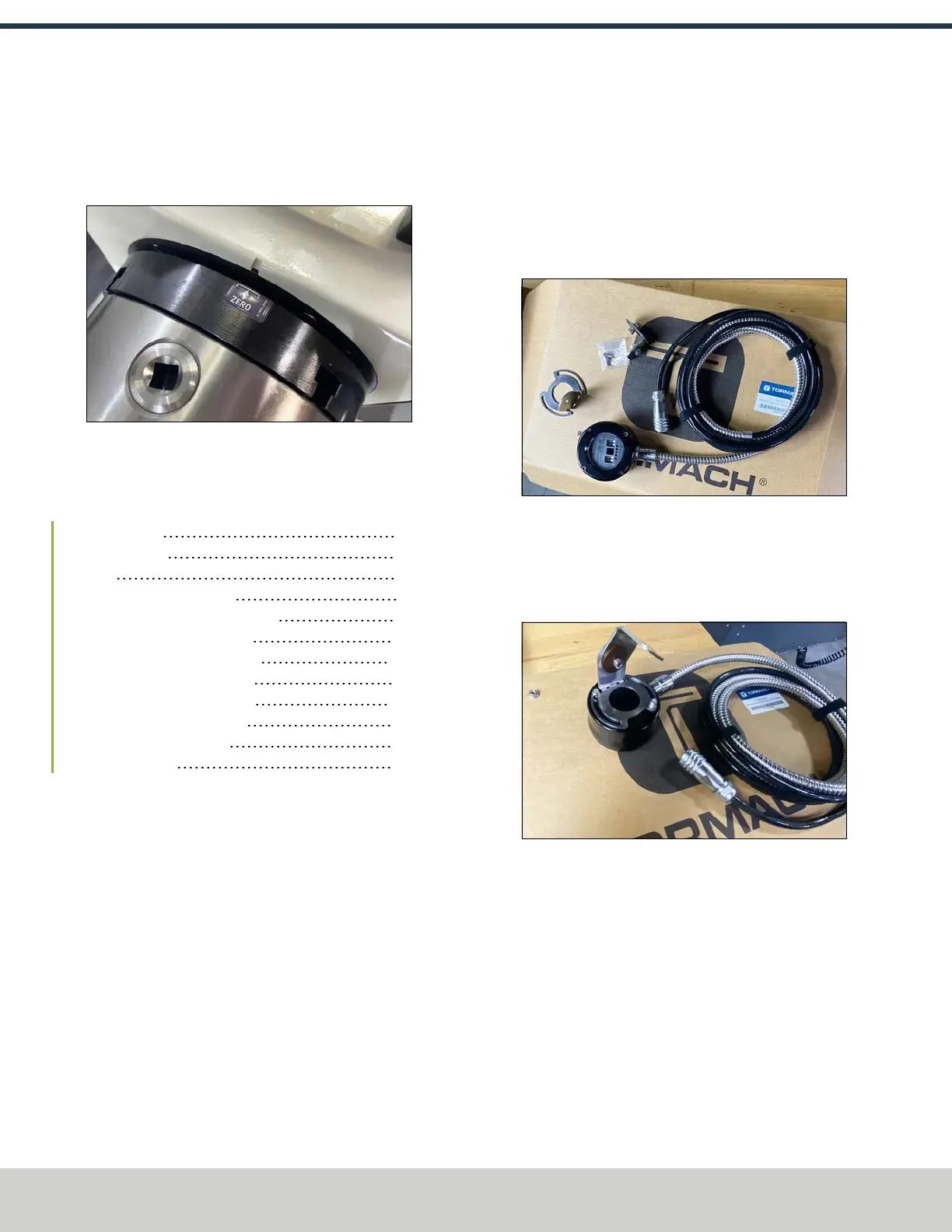
Wireless Receiver Installation
1. Identify the wireless receiver (PN51515), brackets, and
hardware included in this kit.
Figure 4-219: Wireless receiver kit contents.
2. Attach the circular bracket to the wireless receiver using
the included hardware and a 3 mm hex wrench.
3. Remove the nut from the angled bracket and discard it.
Then, install it onto the circular bracket.
Figure 4-220: Both brackets installed onto the
wireless receiver.
©Tormach® 2024
Specifications subject to change without notice.
Page 98 UM10811: 1500MX Operator's Manual (Version 0424A)
For the most recent version, see tormach.com/support
4: INSTALLATION