4: INSTALLATION
2. Remove the nine M6 flanged button head cap screws on
the side of the right side spindle cover with a 4 mm hex
wrench. Set the screws aside. Then, loosen or remove
the three screws on the bottom of the spindle head
cover. Remove the cover, and set it aside.
Figure 4-189: Screws securing the right side spindle
cover.
3. Route the tubing from the nozzle up through the hole on
the bottom left of the spindle head casting. Continue up
to the top of the spindle housing, and out through the
top left hole.
Figure 4-190: Tubing routing into the spindle housing.
4. From the back of the machine, route the tubing through
the energy chain, taking care to keep all the contents in
the energy chain free from twists.
Tip! It may help to raise the Z-axis to its
maximum height, and remove a few of the
energy chain cover panels to more easily route
the tubing through the energy chain.
5. Route the tubing between the machine casting and the
electrical cabinet.
Mount the Pump
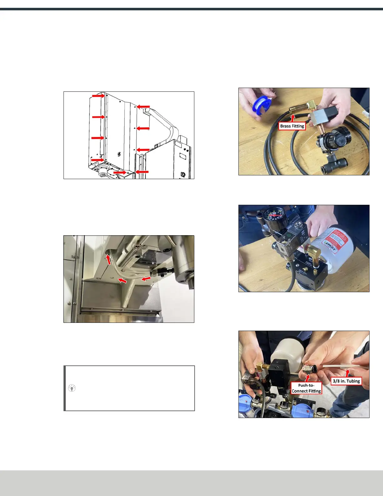
1. Identify the solenoid and pressure regulator assembly
included with this kit. Wrap thread seal tape around the
threads of the brass fitting on the solenoid.
Figure 4-191: Brass fitting on which to use Teflon
tape.
2. Thread the brass fitting on the solenoid onto the pump.
Figure 4-192: Solenoid mounted onto the coolant
pump.
3. Reinstall the push-to-connect fitting that you set aside
earlier onto the 3/8 in. tube.
Figure 4-193: Reinstalling the push-to-connect fitting
onto the tubing.
©Tormach® 2024
Specifications subject to change without notice.
Page 91 UM10811: 1500MX Operator's Manual (Version 0424A)
For the most recent version, see tormach.com/support