4: INSTALLATION
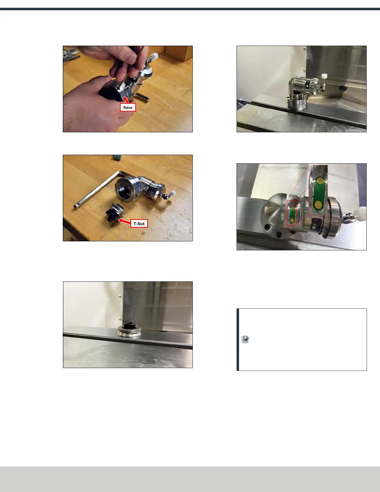
Figure 4-238: Removing the base from the tool setter.
2. Remove and discard the T-nut from the base.
Figure 4-239: T-nut on the tool setter's base.
3. Install the tool setter's base ring to the machine table
with the provided M12 × 1.75 - 30 socket head cap
screw.
Figure 4-240: Base ring installed on the machine
table.
4. Place the tool setter assembly over the base ring and
secure it to the base ring by tightening the set screws.
Figure 4-241: Tool setter installed onto the base ring.
5. Remove the tool setter’s battery door using a flat-blade
screwdriver or similar object.
Figure 4-242: Battery door removed from the tool
setter.
6. Identify the two batteries included with this kit (they're
packaged in the spindle probe's box). Put both batteries
into the tool setter. Replace the battery door onto the
tool setter, and secure it with a screwdriver.
Note: Do not depress the tool setter’s stylus
while inserting the batteries. Depressing the
stylus will cause the tool setter to enter
settings mode. If the stylus is depressed, wait
one minute for the tool setter to exit settings
mode.
Align the Tool Setter's Stylus
1. Place a dial indicator on the spindle, and carefully jog the
indicator's tip into the tool setter's stylus to check that
its face is level.
©Tormach® 2024
Specifications subject to change without notice.
Page 103 UM10811: 1500MX Operator's Manual (Version 0424A)
For the most recent version, see tormach.com/support
 Loading...


