7: PATHPILOT TOOLS AND FEATURES
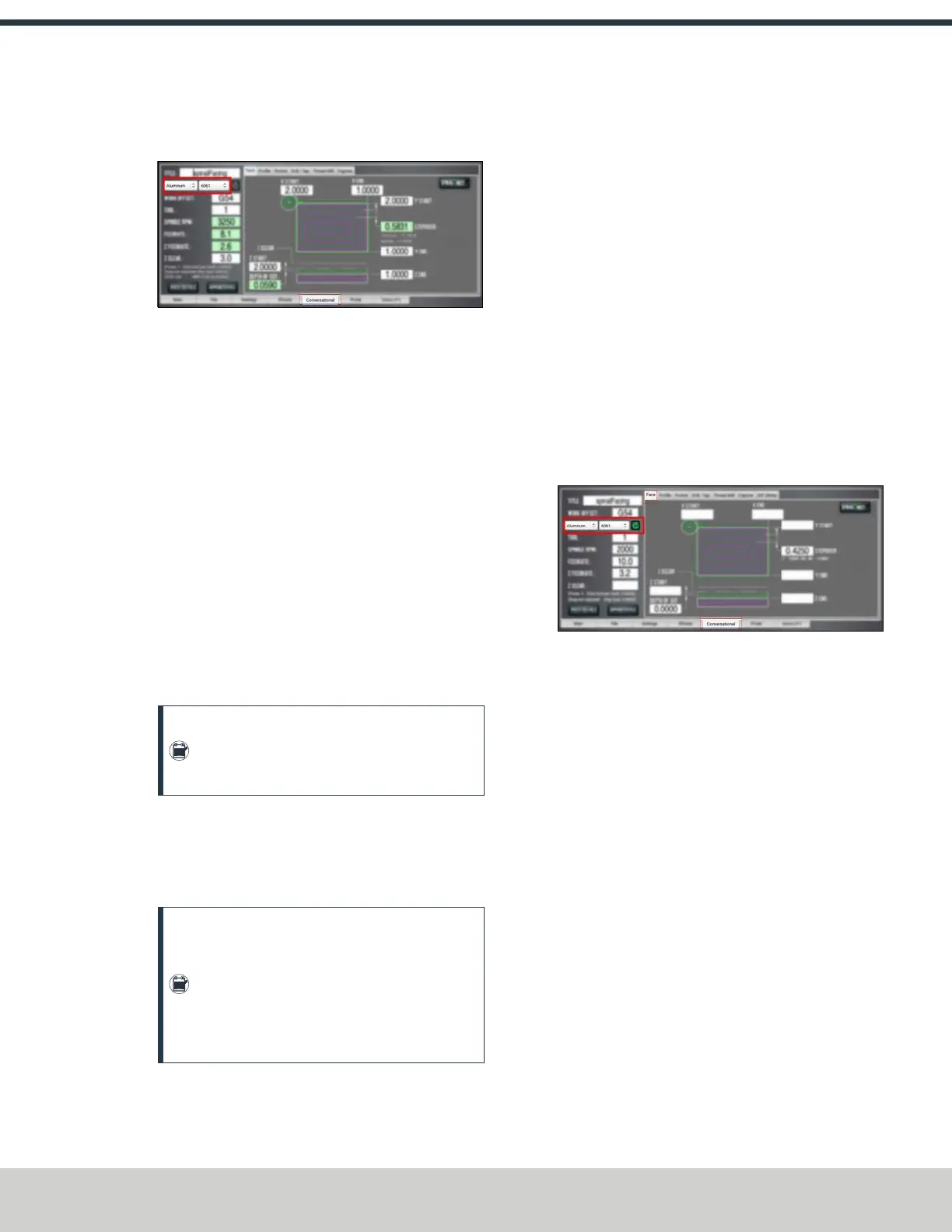
2. From the Conversational tab, locate the Material
dropdowns in the Conversational DROs group.
Figure 7-90: Feeds and speeds suggestions on the
Conversational tab.
3. From the Material dropdown, select your material (like
Aluminum or Plastic).
4. If required, from the Sub-Type dropdown, select the
material sub-type (like -any- or 6061).
5. In the Tool DRO field, type the assigned tool number.
6. Select Refresh (to the right of the Sub-Type dropdown).
The following machining-related DRO fields are
calculated:
l Spindle RPM
l Feedrate
l Z Feedrate
l Depth of Cut
l Stepover
l Peck (if drilling)
Note: After PathPilot calculates values for the
machining-related DRO fields, the background
turns green.
7. (Optional) You can adjust the values in the calculated
DROfields. Adjusting the value in one of these DRO field
doesn't change the value in the other machining-related
DRO fields.
Note: Once you adjust the value in the DRO
field, the background switches from green back
to white. This helps you identify which DRO
fields have suggested values (those with a
green background), and which DRO fields have
values you've supplied (white background).
Refresh DROField Values
The suggested values are no longer valid if:
l You select different material or sub-type values, or if you
type a new value in to the Tool DRO field.
The suggested feeds and speeds are made by taking into
account all of these values. Changing any value requires
you to refresh.
l You select a different Conversational tab.
The suggested feeds and speeds are made by taking into
account the current, specific conversational operation.
Changing your conversational operation requires you to
refresh the feeds and speeds values.
When the feeds and speeds are no longer valid, the Refresh
button turns green, and the machining-related DRO field
backgrounds switch from green to white, as shown in the
following image.
Figure 7-91: Refresh button on the Conversational tab.
Use Additional Provided Information
The following tips are displayed based on the calculations that
PathPilot is performing:
l
Chip Load Information Chip load — the amount of
material removed per tooth — is based on the number
of flutes, RPM, and feed rate.
Chip thinning takes the stepover (the horizontal depth of
cut into the workpiece) into account, and provides the
actual chip load.
As the stepover value decreases, the actual chip load
decreases. If the stepover is too small, the cutter may
not have enough contact with the material to cut —
effectively resulting in premature tool wear.
©Tormach® 2024
Specifications subject to change without notice.
Page 153 UM10811: 1500MX Operator's Manual (Version 0424A)
For the most recent version, see tormach.com/support

 Loading...

