4: INSTALLATION
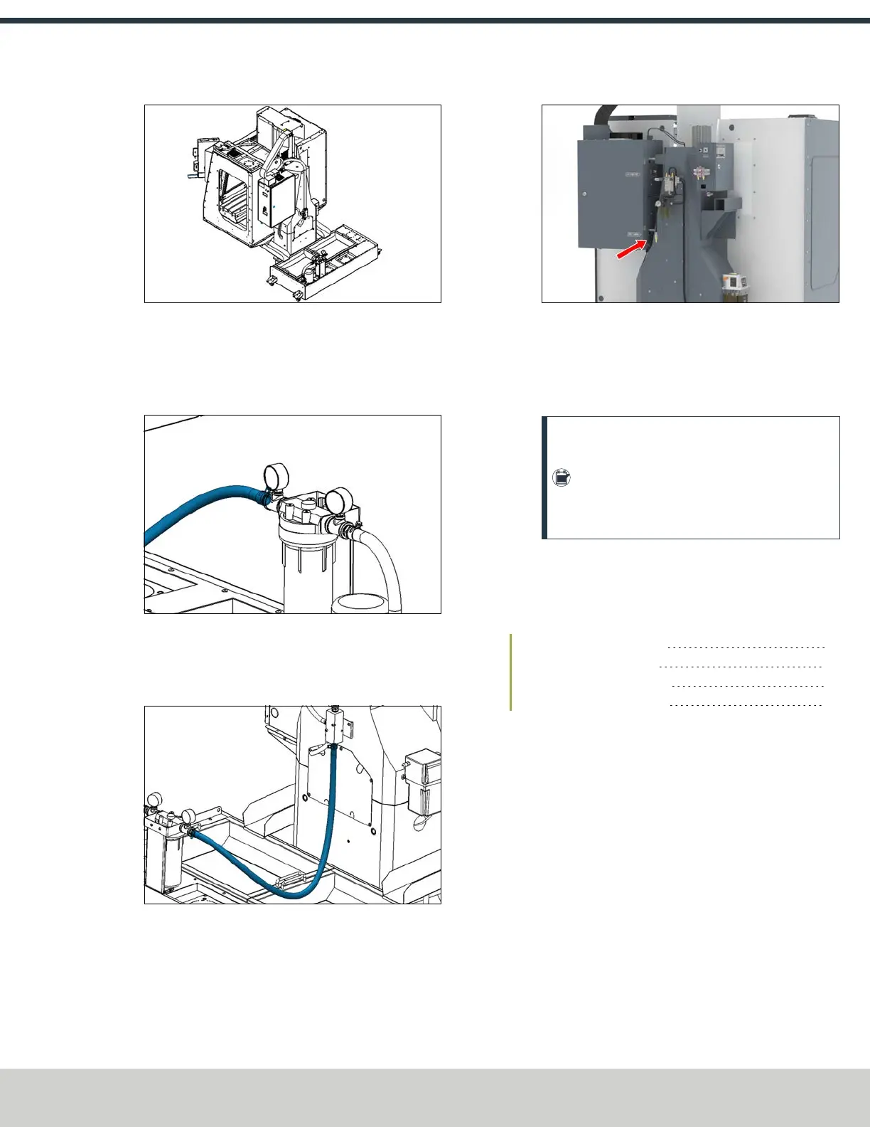
Figure 4-91: Coolant tank behind the machine.
2. Identify the 4 ft, 1 in. ODhose (PN 51608) included with
this kit. Connect one end to the barbed fitting on the
outlet of the coolant filter with a pair of pliers and one
hose clamp (PN51558).
Figure 4-92: Hose connected to the coolant filter.
3. Connect the loose end of the hose to the barbed fitting
on the bottom of the coolant manifold with a pair of
pliers and one hose clamp (PN51558).
Figure 4-93: Hose connected to the coolant manifold.
4. Plug the flood coolant pump's power cable into the Flood
Coolant Power outlet on the side of the electrical cabinet
(on the side that's closest to the column).
Figure 4-94: Flood coolant outlet on the side of the
electrical cabinet.
5. After setting up the flood coolant kit, test the enclosure
for coolant leaks. Identify and seal any areas requiring
extra sealant.
Note: If you received a factory-assembled
machine, the enclosure panels may have
shifted during the shipping process. It's crucial
to test the enclosure for leaks even if your
machine was assembled at the factory.
4.7 VERIFY THE INSTALLATION
After installing the base machine, you must verify the
installation. Complete the following steps in the order listed:
4.7.1 Power on the Machine 65
4.7.2 Verify Axes Function 67
4.7.3 Verify Spindle Function 67
4.7.4 Power off the Machine 67
4.7.1 Power on the Machine
1. Use a multimeter to verify that the electrical service in
your location meets the following requirements. If your
location does not meet these requirements, do not
install the machine. Instead, you must consult with a
local electrician about your options.
l
Primary Power RequiredSingle-Phase 230 Vac,
50/60 Hz
©Tormach® 2024
Specifications subject to change without notice.
Page 65 UM10811: 1500MX Operator's Manual (Version 0424A)
For the most recent version, see tormach.com/support