4: INSTALLATION
14. Connect the motor power cable to its 4-pin molex
connector on the ATC electrical cabinet.
Figure 4-128: Connecting the motor power cable to
the ATC's electrical cabinet.
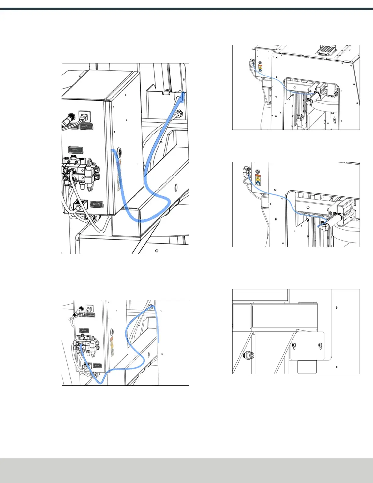
15. Connect the airline labeled Blaster between the rear of
the ATC's motor box and the valve without regulators on
the ATC's electrical cabinet.
Figure 4-129: Connecting the 1/4 in. pneumatic hose
to the ATC's electrical cabinet.
16. Connect the airline labeled Tray In between the fitting of
the pneumatic actuator (furthest away from the spindle)
to the right-hand outlet of the valve with regulators.
17. Connect the airline labeled Tray Out between the
pneumatic actuator's tray out fitting (nearest to the
spindle) to the left-hand valve outlet with regulators.
18. Connect the airline labeled Air Input between the
remaining open valve and the mill's manifold.
19. Find the mount gap plate (PN52450). Install it from the
outside with two M5 button head screws.
Figure 4-130: Mount gap plate installed.
Level the ATC
1. With the air input disconnected, move the ATC to the
tray out position. Insert a BT30 tool holder with a 1/2 in.
rod into the tool tray.
©Tormach® 2024
Specifications subject to change without notice.
Page 75 UM10811: 1500MX Operator's Manual (Version 0424A)
For the most recent version, see tormach.com/support