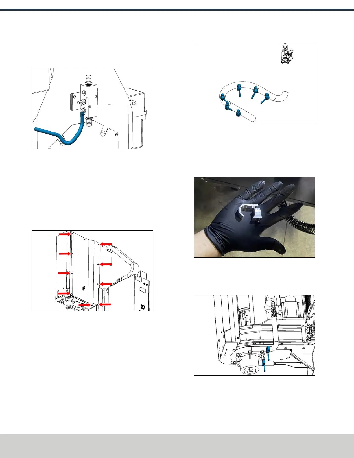
11. Install the loose end of the hose onto the 1/2 in. barbed
elbow fitting on the coolant manifold with a hose clamp
(PN51679) and a pair of pliers.
Figure 4-149: Hose installed onto the coolant
manifold.
Install the Flood Coolant Ring
1. On the front of the machine, remove the nine M6
flanged button head cap screws on the side of the right
side spindle cover with a 4 mm hex wrench. Set the
screws aside. Then, loosen or remove the three screws
on the bottom of the spindle head cover. Remove the
cover, and set it aside.
Figure 4-150: Screws securing the right side spindle
cover.
2. Identify the four swiveling coolant nozzles (PN38348)
and the coolant ring that are included in the kit. Install
each nozzle into the coolant ring with a 17 mm wrench.
Tighten the nozzles until they're pointed toward the
center of the ring.
Figure 4-151: Coolant ring assembly.
3. Identify the two coolant ring mounts (PN51249)
included in this kit. Place one coolant ring mount on the
right side of the coolant ring (the side opposite of the
barbed fitting), and loosely install the coolant ring mount
on the right side of the spindle with a 4 mm hex wrench.
Figure 4-152: Coolant ring mount.
4. Slide the remaining coolant ring mount under the left
side of the coolant ring. Then, tighten both screws with a
4 mm hex wrench.
Figure 4-153: Coolant ring mounted to t he bottom of
the spindle head casting.
©Tormach® 2024
Specifications subject to change without notice.
Page 82 UM10811: 1500MX Operator's Manual (Version 0424A)
For the most recent version, see tormach.com/support
4: INSTALLATION