7: PATHPILOT TOOLS AND FEATURES
3. From the PathPilot interface, in the Tool DROfield, type
the number of the tool.Then select the Enter key.
Figure 7-55: Tool DROfield.
4. Slowly jog the Z-axis down (-Z) to contact the Tool
Height Setter. Stop jogging when the Tool Height Setter
reads zero, which indicates that it's compressed to the
height of the ground surface. Verify that the indicator
rotated around the dial the same number of times as
when you calibrated the Tool Height Setter.
5. From the PathPilot interface, on the Offsets tab, in the
Tool Table, select the tool for which you previously wrote
a description.
6. In the Touch Z DRO field, type the height of the Tool
Height Setter. Then select the Enter key.
Figure 7-56: Touch ZDROfield and button.
7. Select Touch Z.
The length of the tool is stored in the Tool Table
window.
8. From the Tool Table window, in the Length column,
verify that the length of the tool is correct.
9. In the Diameter column, type the diameter of the tool.
Then select the Enter key.
10. Jog the Z-axis up (+Z).
You've completed the procedure to measure a tool
offset. Repeat this procedure for any remaining tooling
you have. Once you're done adding tool length offsets,
switch back to your work coordinate system.
7.3.3 Set Work Offsets
To set the current axis location to zero in the active work
coordinate system:
Select Zero [Axis].
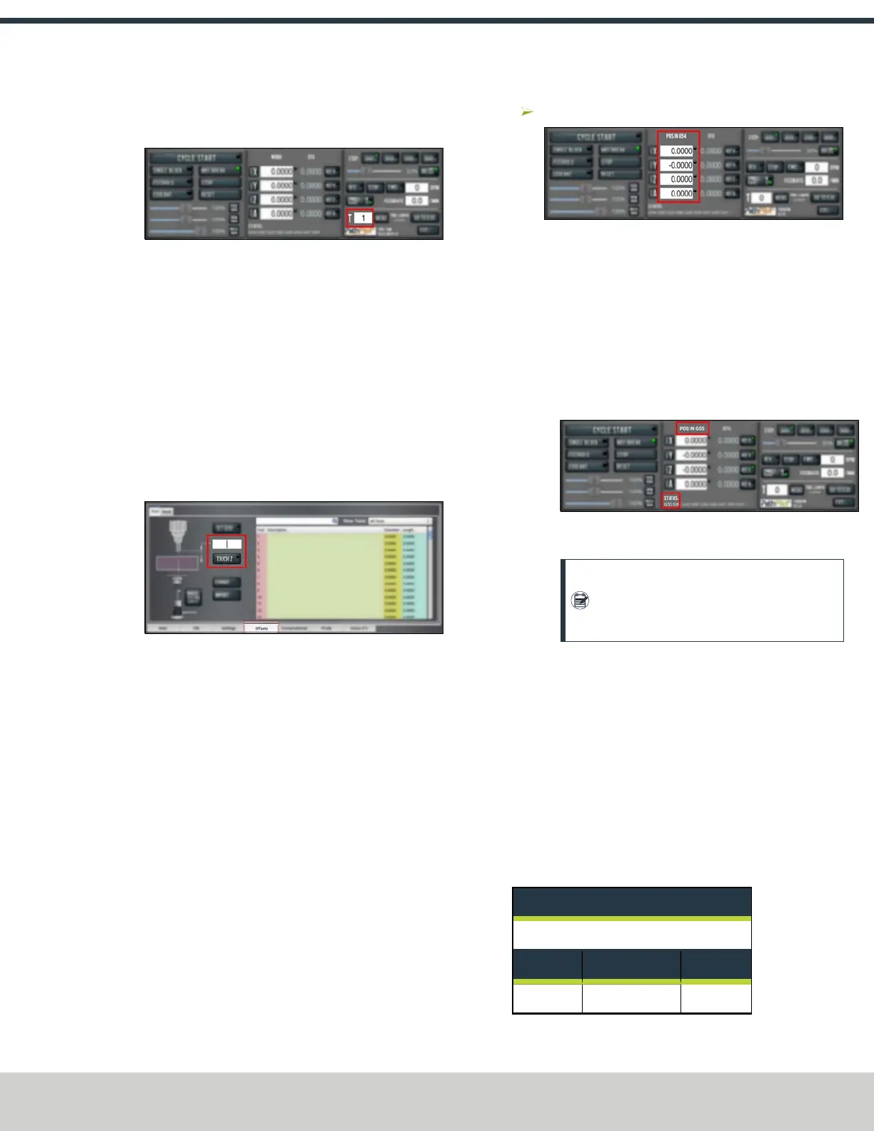
Figure 7-57: Work Offset DRO fields.
To change work offsets:
1. On the Main tab, in theMDILine DROfield, type the
new work offset to activate (for example, G55). Then
select the Enter key.
2. The new work offset displays in the following locations
in the PathPilot interface:
l The Status read-only DROfield.
l Above the Work Offset DRO fields.
Figure 7-58: Work offset indicated in the PathPilot
interface.
Note: The values in the Work Offset
DROfields update to indicate the new
location of each axis in the new work offset.
For more information on using work offsets, see "About Work
Offsets" (page170).
About Work Offsets
Work offsets allow you to think in terms of X, Y, and Z
coordinates with respect to the part, rather than thinking of
them with respect to the machine position. This means that
you can jog the machine to an arbitrary location (like the end
of a workpiece) and call that location zero.
You can save up to 500 work offsets in PathPilot. The naming
structure varies based on the offset number, as detailed in the
following table.
Work Offset Naming
Offsets 1-9 (Use either name)
Offset Extended Name Name
1 G54.1 P1 G54
©Tormach® 2024
Specifications subject to change without notice.
Page 143 UM10811: 1500MX Operator's Manual (Version 0424A)
For the most recent version, see tormach.com/support