Use a Tool Height Setter to Measure Tools
This procedure sets the tool length offset using a known
reference height and a Tool Height Setter (PN39682).
Complete the following steps in the order listed:
Set a Known Reference Height 142
Verify the Calibration of the Tool Height Setter 142
Measure Tools Using a Known Reference Height 142
Set a Known Reference Height
This procedure sets a new Z zero position for the currently
selected work offset.
To set a known reference height:
1. Identify a precision surface to use as a reference surface
(like a 1-2-3 Block Set), and put it below the spindle on
the machine table. Verify that there's a clear path from
the spindle to the machine table.
2. Set a new, unused work offset (like G55).From the
PathPilot interface, on the Main tab, in the MDI Line
DROfield, type a work offset. Then select the Enter key.
For information, see "Set Work Offsets" (page169).
3. If there's already a tool in the spindle, remove it.
4. From the PathPilot interface, in the Tool DROfield, type
0. Then select the Enter key.
5. Slowly jog the Z-axis down (-Z) until it's 0.04 in. (1 mm)
from the reference surface.
6. Measure the thickness of a piece of paper, and put the
paper on the reference surface. Note the thickness of the
paper for later.
7. While moving the paper back-and-forth across the
reference surface, slowly step the Z-axis down (-Z) until
you feel a light pull on the piece of paper. This indicates
that the paper is contacting the end face of the spindle.
Note: It's easier to use step jogging for this
task. For information on step jogging, see
"About Step Jogging" (page163).
8. From the PathPilot interface, in the Z-axis work offset
DROfield, type the thickness of the piece of paper. Then
select the Enter key.
Figure 7-53: Z-axis work offset DRO field.
The reference surface is now set as the Z zero position in
the current coordinate system.
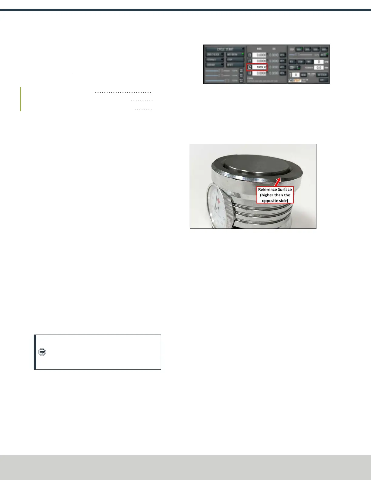
Verify the Calibration of the Tool Height Setter
The higher side of the Tool Height Setter is precision ground.
You can use it as a reference surface to calibrate the tool.
Figure 7-54: Tool Height Setter.
1. Use the provided dowel pin to compress the setting face
of the Tool Height Setter to the level of the ground
reference surface.
2. Adjust the indicator dial's bezel to read zero. Make note
of how many times the indicator rotates around the dial.
3. Measure the height of the ground reference surface
from the bottom surface of the Tool Height Setter with a
calipers. Note the measured height for later.
4. Carefully, without moving the bezel, put the Tool Height
Setter on the reference surface that's on the machine
table.
Measure Tools Using a Known Reference Height
This procedure sets the tool length offset using a known
reference height. If you have not yet done so, you must first set
the Z zero position; go to Set a Known Reference Height.
To measure tools using a known reference height:
1. From the PathPilot interface, on the Offsets tab, find an
unused tool number in the Tool Table window. Then,
type a description for the tool you're measuring.
2. Put the tool holder into the spindle.
©Tormach® 2024
Specifications subject to change without notice.
Page 142 UM10811: 1500MX Operator's Manual (Version 0424A)
For the most recent version, see tormach.com/support
7: PATHPILOT TOOLS AND FEATURES