4: INSTALLATION
4. Fasten the angled bracket of the wireless receiver to the
screw hole nearest to the enclosure door on the inside of
the front right enclosure panel (behind the operator
console) with one M6 × 1.0 - 12 screw.
Figure 4-221: Wireless receiver installed inside the
enclosure, pointing toward the spindle.
5. Adjust the wireless receiver’s bracket to point the
receiver’s panel towards the mill’s spindle. Use zip ties
to secure the wireless receiver's cable out of the way.
6. Remove the Velcro cable ties from the wireless
receiver's cable and set them aside. You'll use them for
cord management later in this procedure.
7. Remove the grommet on the top of the enclosure, and
slide it onto the loose end of the wireless receiver's
cable. Reinstall the grommet back onto the top panel of
the enclosure, and pull the slack through.
8. Route the wireless receiver’s cable back towards the
mill’s electrical cabinet.
Figure 4-222: Wireless receiver's cable routing
through the top panel on the enclosure.
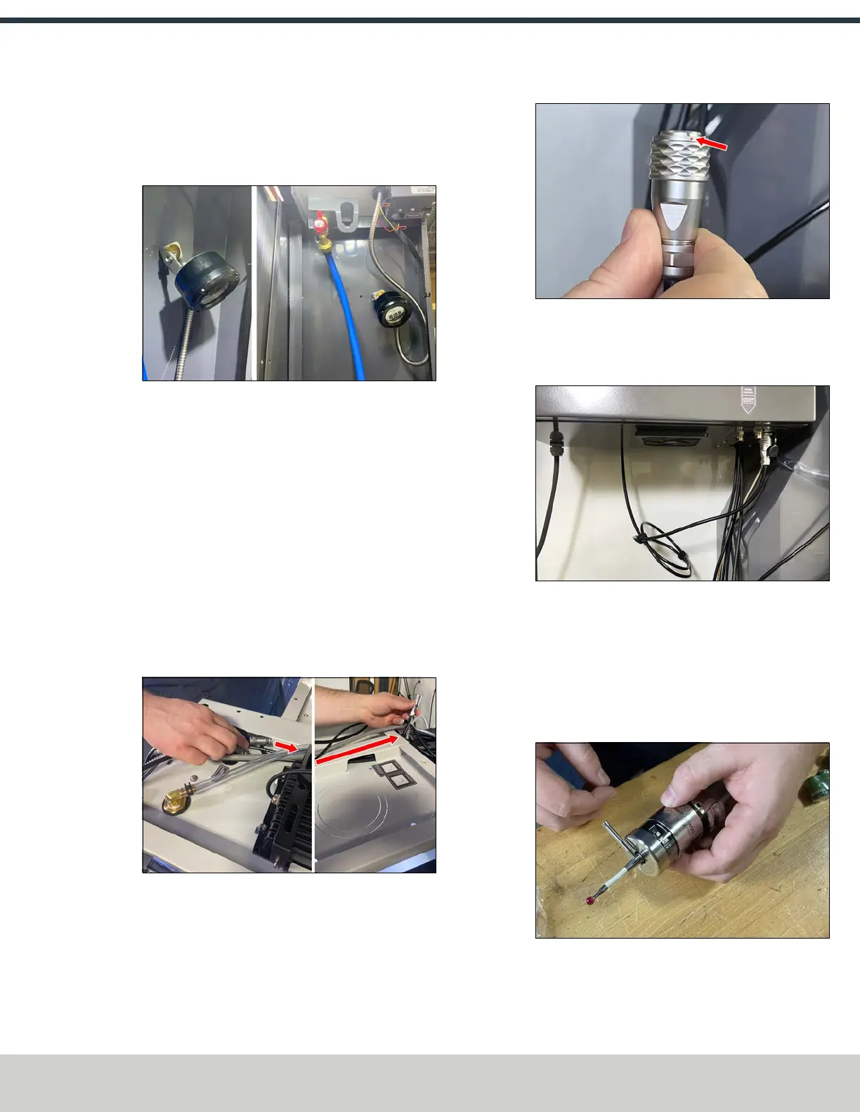
9. Connect the wireless receiver’s cable to the Probe
Control connector on the bottom of the mill's electrical
cabinet. Align the red dots on both the cable and the
connector.
Figure 4-223: Red dot on the cable to align with the
red dot on the connector.
10. Secure the wireless receiver’s cable using the included
Velcro cable ties that you set aside earlier.
Figure 4-224: Cable connection made and secured
with Velcro cable ties.
Wireless Probe Installation and Setup
1. Identify the wireless probe (PN52216) included in this
kit.
2. Thread the probe tip into the wireless probe. Use the
included pin to tighten the probe tip.
Figure 4-225: Tightening the probe tip with the
included pin.
©Tormach® 2024
Specifications subject to change without notice.
Page 99 UM10811: 1500MX Operator's Manual (Version 0424A)
For the most recent version, see tormach.com/support