8. Connect the IEC cable, the EtherCAT cable, and the ATC
STO cable to their respective connectors on the outer left
side of the ATC electrical cabinet.
Figure 4-125: Connecting the IEC, EtherCAT, and
ATCSTOcables to the ATC's electrical cabinet.
9. Remove the cover from the front of the ATC with a 3
mm hex wrench. Set aside the cover and its screws.
10. Connect the ATC encoder/motor power cable (PN 51967)
to the two connectors inside the ATC cover that you
removed in Step 9. Use a #0 Phillips screwdriver to make
the connections.
11. Feed the ATCencoder/motor power cable and the
ATCtray in/out cable (from the actuator) through the
ATC's arm and toward the electrical cabinet.
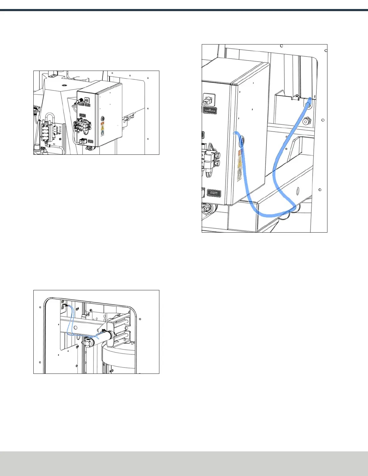
12. Connect the ATC tray in/out cable (PN 51966) and the
ATC encoder/motor power cable (PN 51967) to their
respective connectors on the outer right side of the ATC
electrical cabinet.
Figure 4-126: Connecting the ATCtray in/out and the
ATC encoder/motor power cables to the ATC's
electrical cabinet.
13. Connect the encoder motor cable to its 8-pin molex
connector on the ATC electrical cabinet.
Figure 4-127: Connecting the encoder motor cable to
the ATC's electrical cabinet.
©Tormach® 2024
Specifications subject to change without notice.
Page 74 UM10811: 1500MX Operator's Manual (Version 0424A)
For the most recent version, see tormach.com/support
4: INSTALLATION