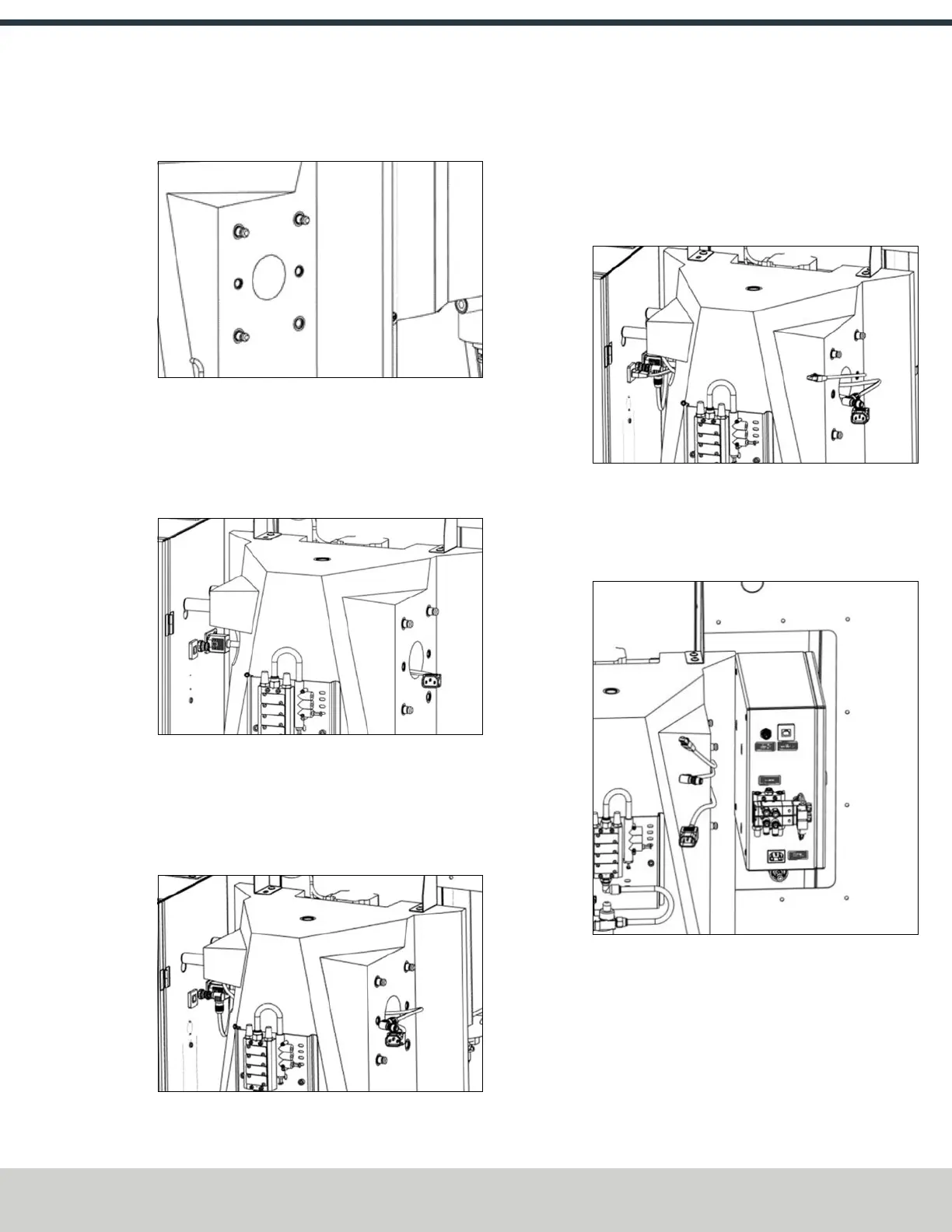
4: INSTALLATION
3. Thread the three M12 × 15 mm standoffs into the
threaded holes as shown in the following image.
Figure 4-120: Installing the standoffs in the threaded
holes.
4. Connect the black IEC cable (PN 51969) to its respective
connector on the right side of the machine's electrical
cabinet. Bring the cable through the column across the
lifting point as shown in the following image.
Figure 4-121: Connecting the black IEC cable to the
machine's electrical cabinet.
5. Connect the EtherCAT cable (PN 51970) to its respective
connector on the right side of the machine's electrical
cabinet. Bring the cable through the column across the
lifting point as shown in the following image.
Figure 4-122: Connecting the EtherCAT cable to the
machine's electrical cabinet.
6. Connect the ATC STO cable (PN 51965) to its respective
connector on the right side of the machine's electrical
cabinet. Bring the cable through the column across the
lifting point as shown in the following image.
Figure 4-123: Connecting the ATCSTOcable to the
machine's electrical cabinet.
7. Using the keyhole slots on the back of the ATC electrical
cabinet, hang the cabinet on the standoffs. Make sure to
adjust the cables so that they don’t get pinched.
Figure 4-124: Installing the ATC's electrical cabinet
onto the standoffs.
©Tormach® 2024
Specifications subject to change without notice.
Page 73 UM10811: 1500MX Operator's Manual (Version 0424A)
For the most recent version, see tormach.com/support