5 Using 3D Guidance in theField
Creating a sloping design surface
WARNING — If you create a ramp or other work platform that is too steep, machines and
vehicles using the ramp or platform could become difficult to control. This could result in
harm to the operator, to others, or damage to the machine. To ensure your safety and the
safety of others, find out what the maximum slope for your site is and make sure you do not
exceed it.
Note – To learn more about the elements that make up a sloping surface, refer to
the GCS900 Grade Control System Reference Manual.
To create a sloping surface design file:
1. From the Select Design File dialog, press New Level, New Slope, or New Map.
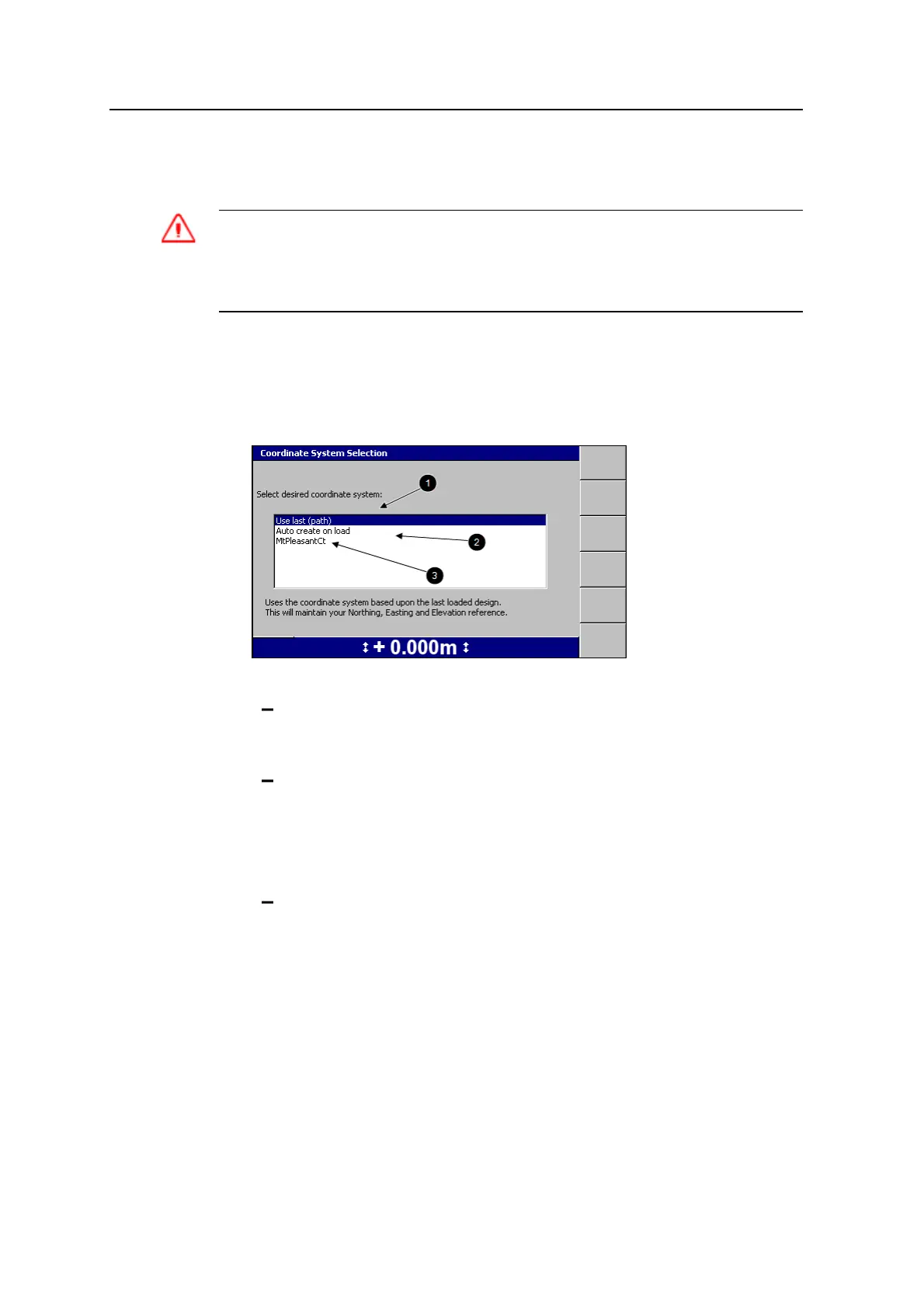
2. Select one of the following options:
1: To use the same coordinate system as the last loaded design, select
Use last (<name>). This option maintains your Northing, Easting and
Elevation reference.
2: To automatically create a new coordinate system based on your current
position, select Auto create on load. (MS9x2-based systems only, with
firmware version 4.40 or later).
Note – This option is only available when no site wide avoidance zone is
loaded.
3: To use an existing coordinate system stored in the root directory of the
control box file system, select the coordinate system name.
3.
Press \. The New Map dialog, the New Design: Level Surface dialog, or the
New Design: Sloping Surface dialog appears.
124 GCS900 GradeControl System for Excavators Operator's Manual