8-17
PWBs > Description for PWB
[CONFIDENTIAL]
(5-3)Connector lists
Destination
• YC1: Engine PWB
• YC2: Backlight PWB
(6) Relay-L PWB
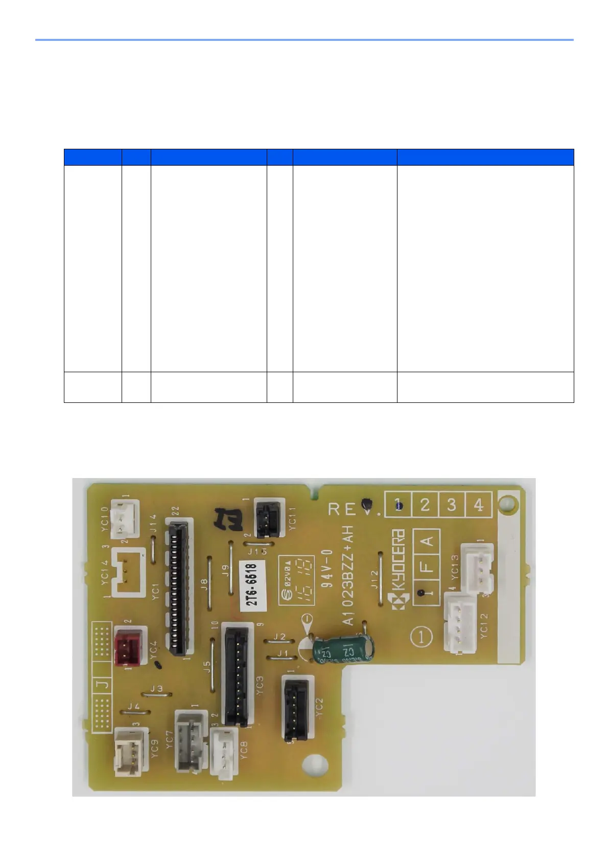
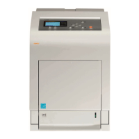
(6-1)PWB photograph
Connector Pins Signal I/O Voltage Description
YC1 1 +3.3V1_F1 I DC3.3V Power source
2 FPRSTN I DC0V/3.3V Reset signal
3 GND - - Ground
4 INT_OK_N O DC0V/3.3V Pressing the OK key on the operation
panel (Return)
5 AIRTEMP O Analog Temperature sensor input signal
6 INT_MENU O DC0V/5V Pressing the Menu key on the operation
panel (Return)
7 +5.0V1_F1 I DC5V Power source
8 P2C_SDAT O DC0V/3.3V Data signal
9 AIRWET O Analog Humid sensor output signal
10 C2P_SDAT I DC0V/3.3V The data signal between panel main
11 WETCLK I DC0V/3.3V (pulse) Humid sensor clock signal
12 FG - - Ground
YC2 1 +5V5 I DC5V Power input
2 BLIGHT O DC0V/5V
Backlight: On/Off