REMOTE:
Frequency reference
(default: 4...20mA)
RUN
FAULT
READY
Analogue input 1 +
Analogue input 1 -
Analogue input 2 +
Analogue input 2 -
Reference output+10 Vref
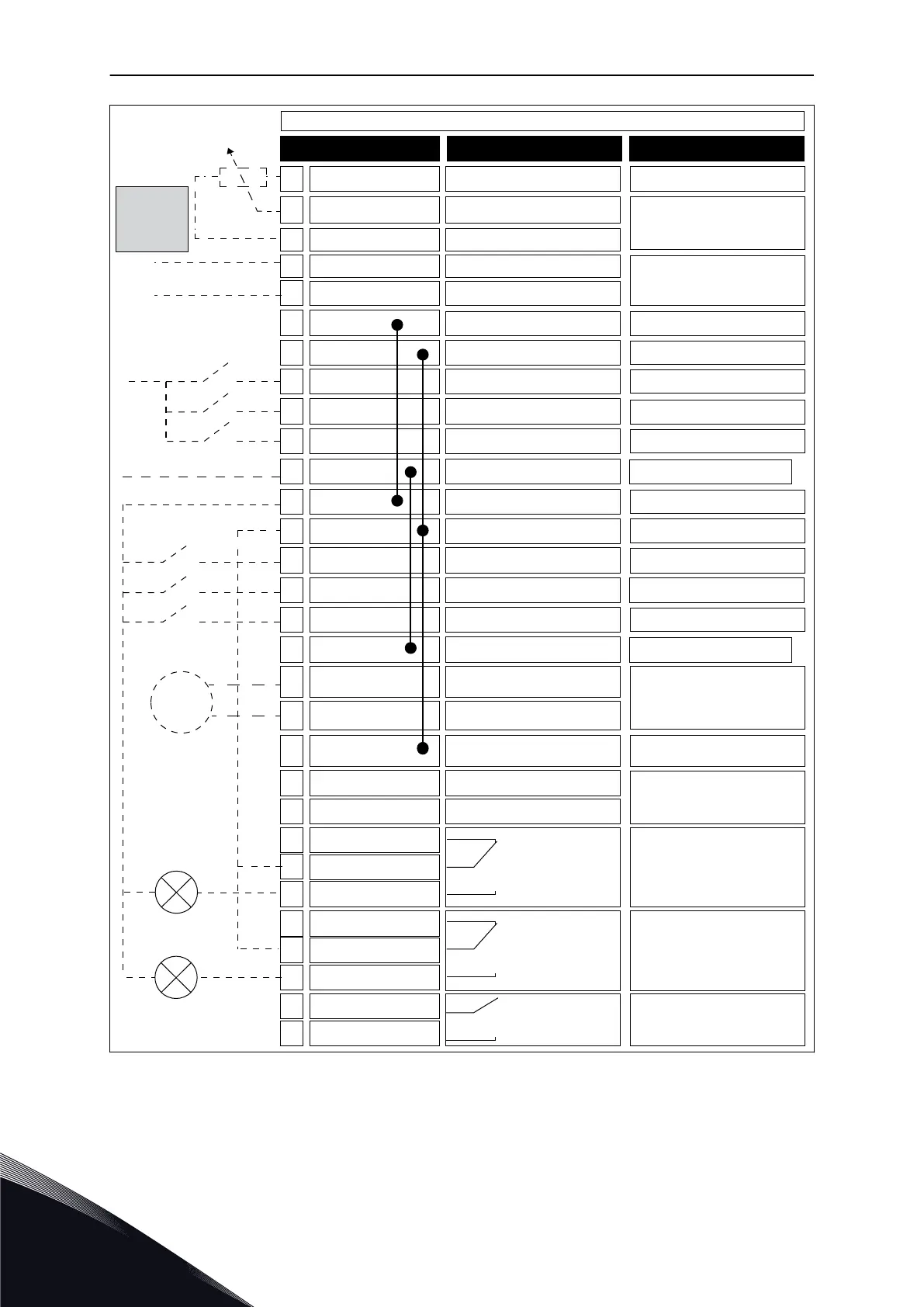
Terminal Signal
1
24V auxiliary voltage24Vout6
Remote reference
(4...20mA)
AI1+2
AI1-
3
AI2+4
AI2-5
AO1+
RUN
18
AO1-/GND19
+24Vin
30
24V auxiliary voltage24Vout
12
I/O groundGND7
I/O groundGND13
Digital input 1DI18
Digital input 2DI29
Digital input 3DI310
Digital input 4DI414
Digital input 5DI515
Digital input 6DI616
Relay output 1RO1/1 NC21
22
RO1/2 CM
RO1/3 NO23
Common for DI1-DI6CM11
Common for DI1-DI6CM
17
Serial bus, negativeRS485A
Serial bus, positiveRS485
B
Relay output 2
Relay output 3
RO2/1 NC24
25
RO2/2 CM
RO2/3 NO26
32
RO3/2 CM
RO3/3 NO33
Description
REMOTE: Start forward
REMOTE: Start reverse
External fault
Output frequency
(default: 0...20mA)
Modbus RTU
BACnet, N2
LOCAL: Start forward
LOCAL: Start reverse
LOCAL/REMOTE
selection
Remote
control ground
Analogue output 1 +
Analogue output 1 -
FAULT
Reference
potentiom-
eter
1...10kΩ
Remote
control
(+24V)
mA
*)
*)
24V auxiliary
input voltage
LOCAL:
Frequency reference
(default: 0...10V)
Standard I/O board
Fig. 6: The default control connections of the Local/Remote application
* = You can isolate the digital inputs from the ground with a DIP switch.
VACON · 22 QUICK STARTUP GUIDE
1
TEL. +358 (0)201 2121 · FAX +358 (0)201 212 205

 Loading...


