Maintenance2124−2/A1
Winterthur Gas & Diesel Ltd.
2/ 7
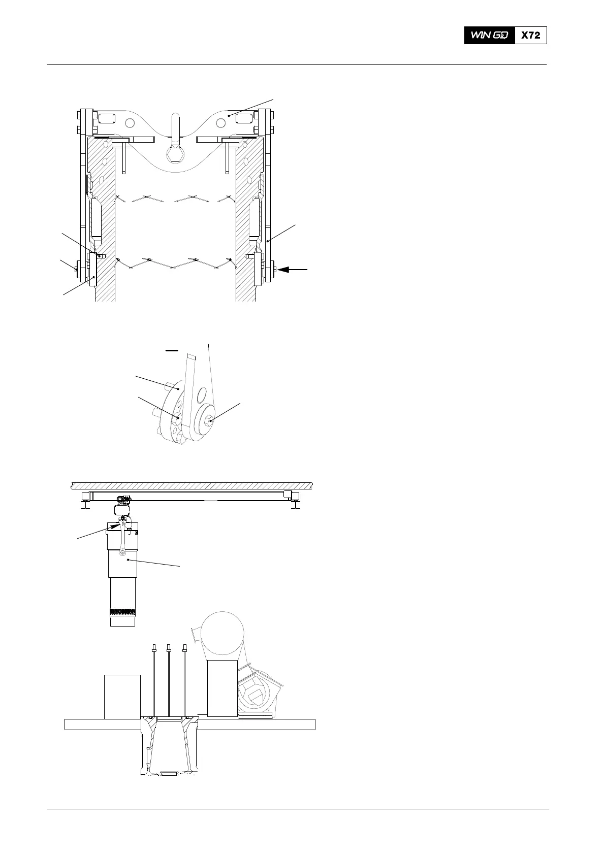
2.1 Lifting Tool − Install
1) Put the two flange couplings (17,
Fig. 2) in position on the cylinder liner.
2) Tighten the five screws (22) in each
flange coupling.
3) Put the lifting tool (94201) in position on
top of the cylinder liner.
4) Apply copper paste to the threads of
the special screws (9).
5) Attach the two holders (23) to the
flange couplings (17) with the special
screws (9).
6) Torque the special screws (9) to
230Nm.
2.2 Cylinder Liner − Lift
1) Connect the crane hook to the shackle
on the lifting tool (94201).
2) Carefully lift the cylinder liner (2).
3) Move the cylinder liner (2) over the rail
unit as shown in Fig. 3.
4) Lower the cylinder liner on to a suitable
wooden underlay.
2.3 Lifting Tool − Removal
1) Remove the two special screws (9,
Fig. 2).
2) Remove the lifting tool (94201) from the
cylinder liner.
3) Remove the screws (22), then remove
the two flanges (17).
4) Remove the crane hook from the
shackle.
2015
Cylinder Liner: Removal and Fitting
WCH02342
94201
17
22
9
I
23
I
9
22
17
Fig. 2
94201
2
WCH02343
Fig. 3

 Loading...


