Maintenance
2138−1/A2
Winterthur Gas & Diesel Ltd.
1/ 5
Removal and Installation
Tools:
1 HP oil pump 94931 1
Connection nipple (G¼ inch)
94934I
1 Hydraulic distributor 94934H 1 HP hose 94935
(with pressure gauge 1 Dismantling tool 94213
0 bar to 25 bar)
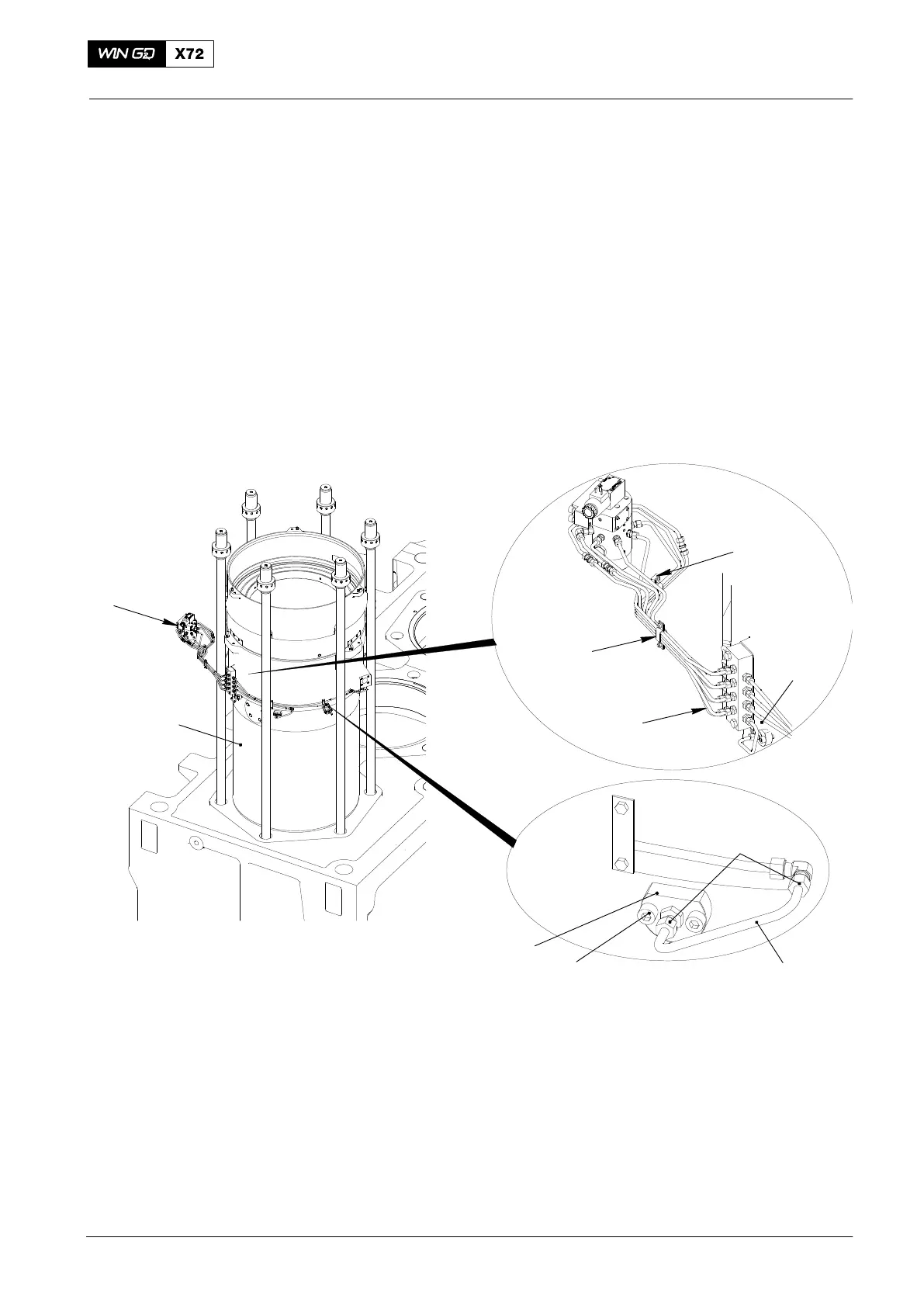
1. General
If it is not necessary to remove the cylinder liner (1, Fig. 1), you must not drain the
cylinder cooling water.
Steps 1) to 3) are only necessary if the cylinder liner (1) must be removed.
1) Remove the two holders (3).
2) Disconnect the eight pipes (4, 5).
3) Seal the pipes (4, 5) with applicable seals to prevent contamination.
WCH02268
2
FREE END
1
Fig. 1
7
8
9
6
3
4
5
3
2. Removal Procedure
1) Loosen the nuts (6) of the unions.
Note: Make sure that you do not damage the oil pipe (7).
2) Disconnect the oil pipe (7).
3) Seal the oil pipe (9) with an applicable plug to prevent contamination.
4) Remove the two bolts (8).
5) Remove the lubricating quill (9).
6) If necessary, do a function check of the lubricating quills (see paragraph 3).
Lubricating Quill
2018−02

 Loading...


