Maintenance
2303−1/A1
Winterthur Gas & Diesel Ltd.
9/ 12
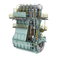
5) Install the lifting tool 94235 below the
piston rod gland (5). Make sure there is
contact between piston rod gland and
lifting tool.
6) Slightly tighten the four bolts (8).
7) Tighten the four bolts (6) with 30 Nm.
8) Remove eight bolts (7) together with
locking plates.
9) Remove working support 94143.
10) Use turning gear to turn the
crosshead (2) to B.D.C.
11) Install working support 94143.
12) Attach one chain block 94016-009 with
shackle 94018B on each side of the
column.
13) Install two eye bolt 94045-M12 on the
piston gland box (1, Fig.14).
14) Attach the hooks of the chain blocks to
the eye bolts on the piston rod gland
and apply tension to the chains.
15) Mark the position of the piston rod
gland on the piston rod (7).
16) Remove four bolts (4) from the piston
rod gland (1).
17) Slowly loosen four bolts (3) on the
lifting tool (94235), just as much as
needed to pull the lifting tool 94235
together with the support (5) down.
18) Pull the lifting tool 94235 down to the
piston rod foot (6).
2016−02
Replace, Assembling, Wear Measurement
2
Fig. 13
94235
6
7
8
94143
Fig. 14
2
94018B
94016-009
94045-M12
1
I
I
1
94045-M12
3
4
94235
5
6
7
MARK


 To Next Page