Maintenance
2722−1/A1
Winterthur Gas & Diesel Ltd.
3/ 3
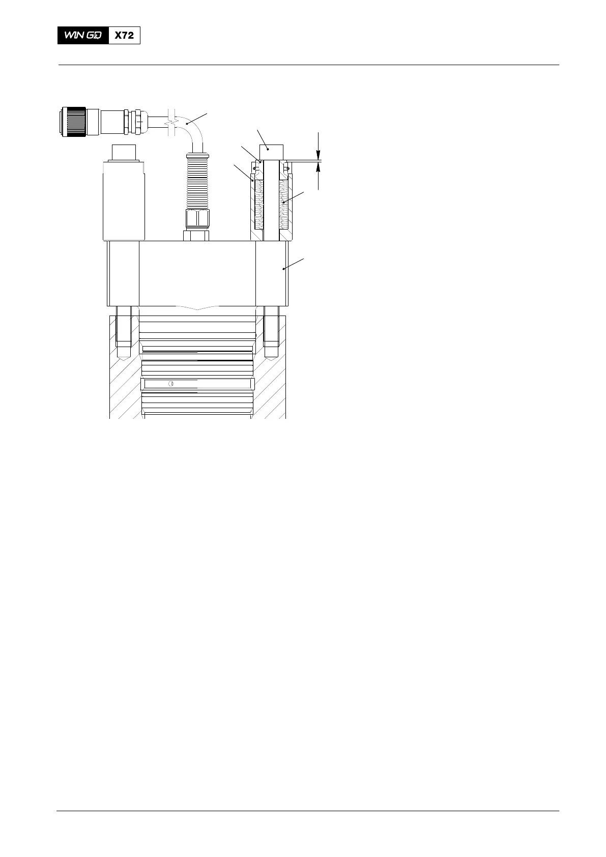
10) If the spring cage (3, Fig. 3) was
disassembled, make sure that the cup
springs (1) are installed as shown (four
sets of six cup springs).
Note: A correct assembled spring cage
has a protrusion of the
uncompressed spring guide (4) of
Y = 1.8mm
11) Put the spring cages (3) in position on
the injection valve (2).
12) Apply Never-Seez NSBT to the threads
and the seating surface of the two
screws (5, Fig. 3).
13) Tighten equally the two screws (5) until
the spring guide (4) is flush with the
spring cage (3); Y = 0mm.
Note: The tightening force is relatively
low compared to the installation
force.
14) Connect the cable (6) to terminal box
95.4.
15) Install the applicable HP fuel pipe, refer
to 8733−1.
3. Storage Area
You must make sure that the storage area is clean, dry and has no contamination in
the air.
2015
WCH02401
Fig. 3
Y
2
1
3
4
5
6

 Loading...


