Maintenance5562−3/A1
Winterthur Gas & Diesel Ltd.
4/ 5
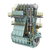
9) Apply lubricating oil to all running
surfaces (RS).
10) Push piston rod (4, Fig. 5) together with
piston (2) into flange (3). Check for
smooth running (full stroke and
turning).
11) Slide the piston (2) together with flange
into the valve block (1).
12) Apply Never Seez NSBT to the threads
and contact surfaces of the twelve
screws (8).
13) Tighten the twelve screws (8) equally
by hand and check for smooth running.
14) Tighten the twelve screws (8) with
60Nm and check again for smooth
running.
15) Put a new O-ring (7) to the cover (5).
16) Install the cover (5) and tighten the
three screws (9).
5. Installation
1) Make sure that the dowel pins are in
the fuel rail.
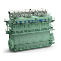
2) Clean the sealing surface in the valve
block (1, Fig. 6) and the lip seal (6). It is
highly recommended to install a new lip
seal (6).
3) Install the lip seal (6).
4) Clean the mounting area on the fuel rail
and the valve block.
5) Put the flow limiting valve carefully on
the correct position on the fuel rail.
6) Apply Never Seez NSBT to the threads
and contact surfaces of the eight bolts
(2).
7) Put in the eight bolts (2) together with
distance sleeves into the valve block
and tighten the bolts (2) by hand.
8) Tighten the eight bolts (2) with a torque
of 60Nm.
2015
Injection Control Unit: Removal and Installation
1
9
WCH03229
Fig. 5
5
4
8 3
3
2
RS
1
RS
8
5
9
7
1
2
6
2 1
WCH03229
Fig. 6


 To Next Page