7 Series FPGAs SelectIO Resources User Guide www.xilinx.com 125
UG471 (v1.10) May 8, 2018
IDELAYCTRL
RDY - Ready
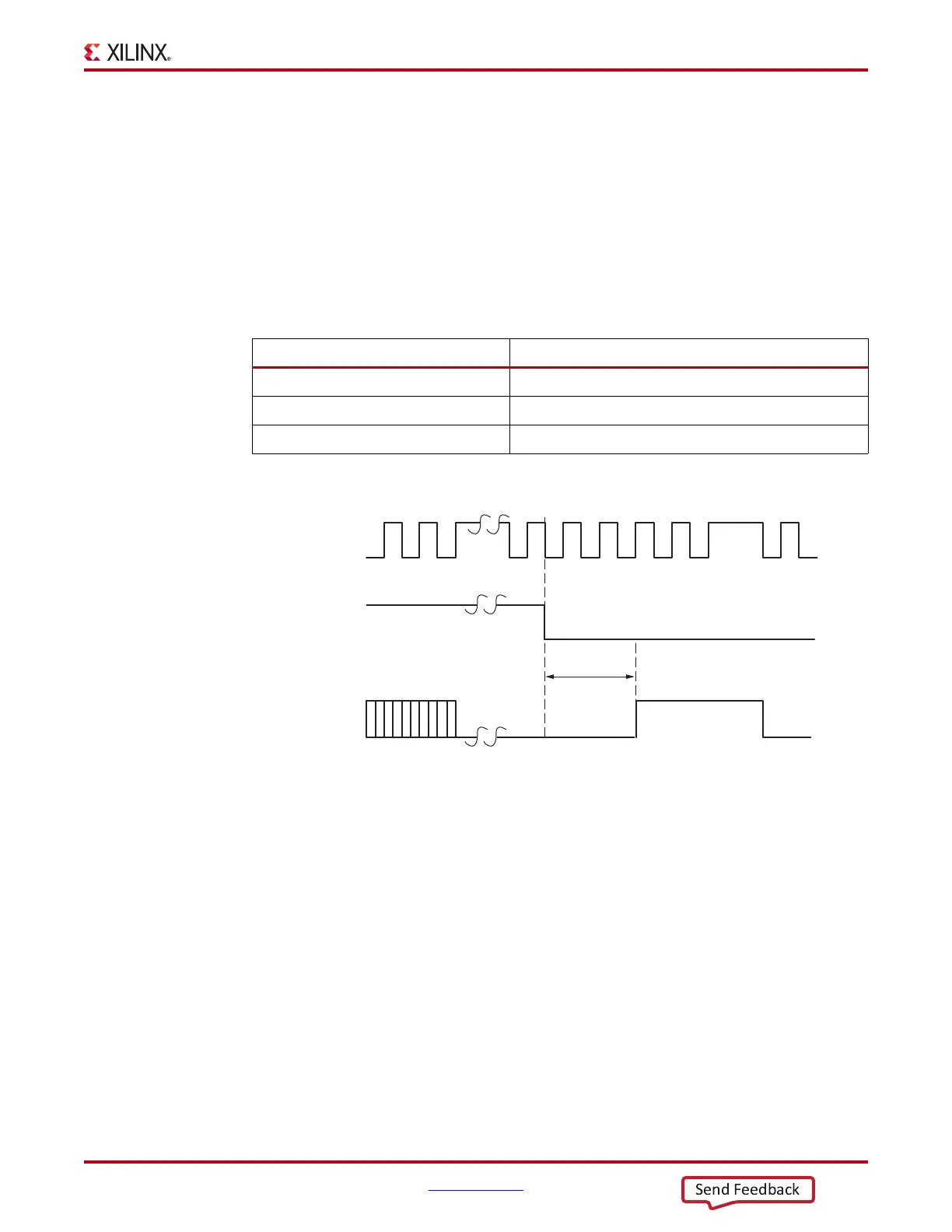
The ready (RDY) signal indicates when the IDELAY and ODELAY modules in the specific
region are calibrated. The RDY signal is deasserted if REFCLK is held High or Low for
more than one clock period. If RDY is deasserted Low, the IDELAYCTRL module must be
reset. The implementation tools allow RDY to be unconnected/ignored. Figure 2-15
illustrates the timing relationship between RDY and RST.
IDELAYCTRL Timing
Table 2-9 shows the IDELAYCTRL switching characteristics.
As shown in Figure 2-15, the 7 series FPGA IDELAYCTRL RST is an edge-triggered signal.
IDELAYCTRL Locations
IDELAYCTRL modules exist in every I/O column in every clock region. An IDELAYCTRL
module calibrates all the IDELAYE2 and ODELAYE2 modules within its clock region. See
the 7 Series FPGA Clocking User Guide for the definition of a clock region.
Figure 2-16 illustrates the relative locations of the IDELAYCTRL modules.
Table 2-9: IDELAYCTRL Switching Characteristics
Symbol Description
F
IDELAYCTRL_REF
REFCLK frequency
IDELAYCTRL_REF_PRECISION REFCLK precision
T
IDELAYCTRLCO_RDY
Reset/Startup to Ready for IDELAYCTRL
X-Ref Target - Figure 2-1 5
Figure 2-15: Timing Relationship Between RST and RDY
RST
REFCLK
RDY
ug471_c2_13_011811
T
IDELAYCTRLCO_RDY
 Loading...

