7 Series FPGAs SelectIO Resources User Guide www.xilinx.com 167
UG471 (v1.10) May 8, 2018
Output Parallel-to-Serial Logic Resources (OSERDESE2)
OSERDESE2 Width Expansion
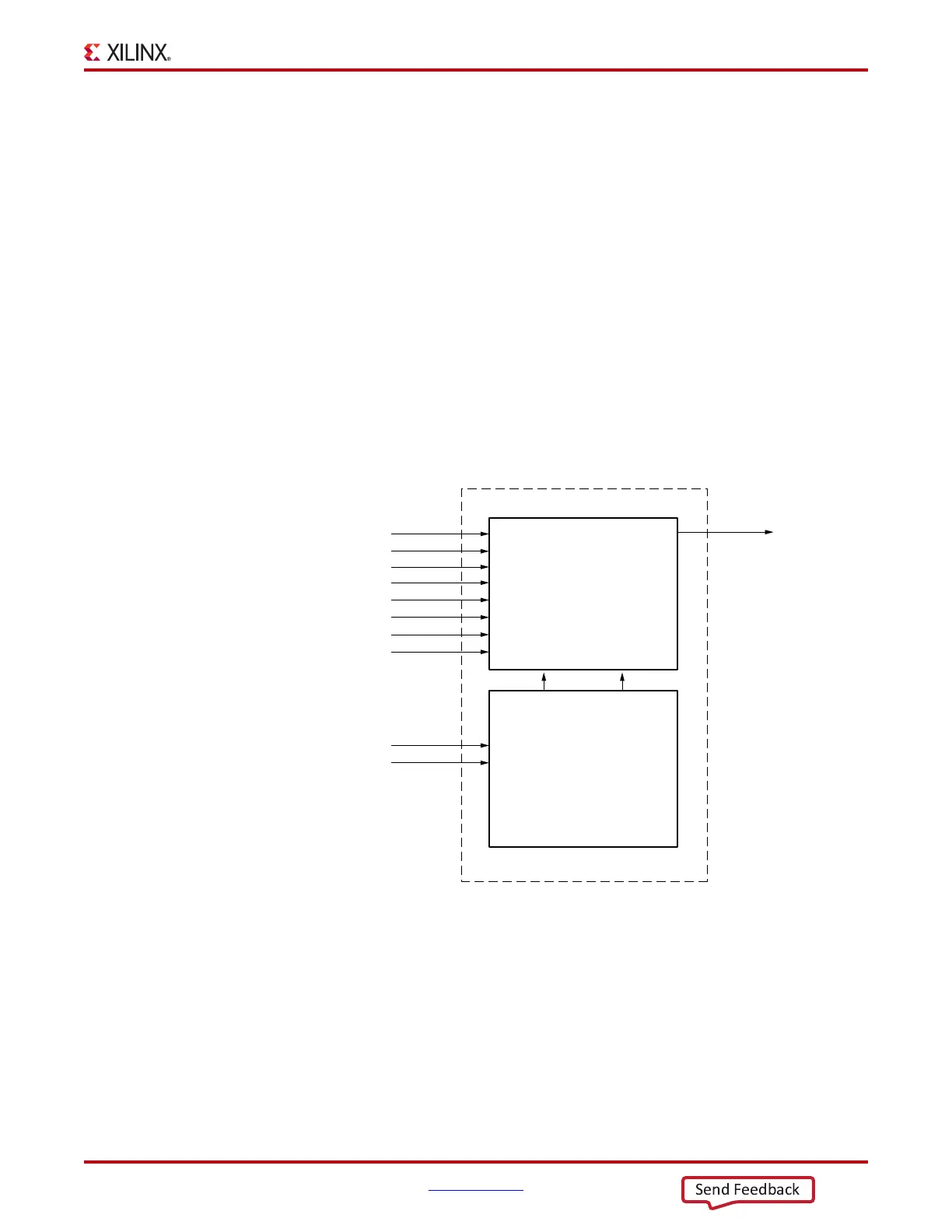
The OSERDESE2 modules be used to build a parallel-to-serial converter larger than 8:1. In
every I/O tile there are two OSERDESE2 modules; one master and one slave. By
connecting the SHIFTIN ports of the master OSERDESE2 to the SHIFTOUT ports of the
slave OSERDESE2, the parallel-to-serial converter can be expanded to up to 10:1 and 14:1
(DDR mode only). For a differential output, the master OSERDESE2 must be on the
positive (_P pin) side of the differential output pair. When the output is not differential, the
output buffer associated with the slave OSERDESE2 is not available and width expansion
cannot be used.
When using complementary single-ended standards (e.g., DIFF_HSTL and DIFF_SSTL),
width expansion might not be used. This is because both OLOGICE2/3 blocks in an I/O
tile are used by the complementary single-ended standards to transmit the two
complementary signals, leaving no OLOGICE2/3 blocks available for width expansion
purposes.
Figure 3-15 illustrates a block diagram of a 10:1 DDR parallel-to-serial converter using the
master and slave OSERDESE2 modules. Ports D3–D4 are used for the last two bits of the
parallel interface on the slave OSERDESE2 in this case.
X-Ref Target - Figure 3-15
Figure 3-15: Block Diagram of OSERDESE2 Width Expansion
OQ
Data Inputs[0:7]
Data Inputs[8:9]
OSERDESE2
(Slave)
SERDES_MODE=SLAVE
OQ
OSERDESE2
(Master)
SERDES_MODE = MASTER
D1
D2
D3
D4
D5
D6
D1
D2
D3
D4
D5
D6
SHIFTIN1 SHIFTIN2
SHIFTOUT1 SHIFTOUT2
D7
D8
D7
D8
Data Out
ug471_c3_15_111011