146 www.xilinx.com 7 Series FPGAs SelectIO Resources User Guide
UG471 (v1.10) May 8, 2018
Chapter 3: Advanced SelectIO Logic Resources
ISERDESE2 Ports
Registered Outputs – Q1 to Q8
The output ports Q1 to Q8 are the registered outputs of the ISERDESE2 module. One
ISERDESE2 block can support up to eight bits (i.e., a 1:8 deserialization). Bit widths greater
than eight (up to 14) can be supported in DDR mode only. See
ISERDESE2 Width Expansion.
The first data bit received appears on the highest order Q output.
The bit ordering at the input of an OSERDESE2 is the opposite of the bit ordering at the
output of an ISERDESE2 block, as shown in Figure 3-3. For example, the least significant
bit A of the word FEDCBA is placed at the D1 input of an OSERDESE2, but the same bit A
emerges from the ISERDESE2 block at the Q8 output. In other words, D1 is the least
significant input to the OSERDESE2, while Q8 is the least significant output of the
ISERDESE2 block. When width expansion is used, D1 of the transmitter OSERDESE2 is the
least significant input, while Q8 of the receiver ISERDESE2 block is the least significant
output.
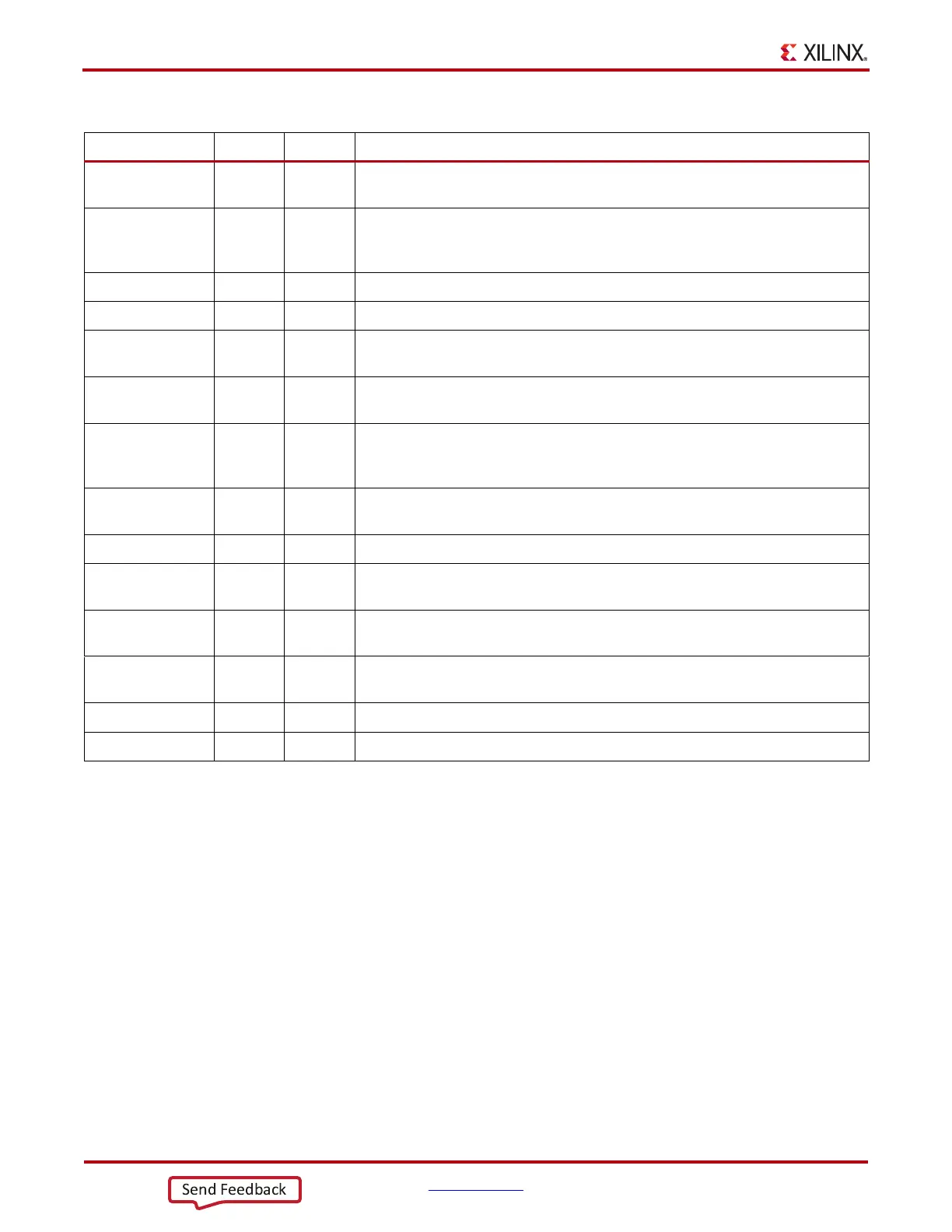
CLK Input 1 High-speed clock input. Clocks serial input data stream. See High-Speed
Clock Input - CLK.
CLKB Input 1 Second High speed clock input only for MEMORY_QDR mode. Always
connect to inverted CLK unless in MEMORY_QDR mode. See
MEMORY_QDR Interface Type.
CE1, CE2 Input 1 (each) Clock enable inputs. See Clock Enable Inputs - CE1 and CE2.
RST Input 1 Active High reset. See Reset Input - RST.
CLKDIV Input 1 Divided clock input. Clocks delay element, deserialized data, Bitslip
submodule, and CE unit. See Divided Clock Input - CLKDIV.
CLKDIVP Input 1 Only supported via the MIG tool. Sourced by PHASER_IN divided CLK in
MEMORY_DDR3 mode. All other modes connect to ground.
OCLK Input 1 High-speed clock input for memory applications. See High-Speed Clock for
Strobe-Based Memory Interfaces and Oversampling Mode - OCLK. (This
clock resource is shared with the OSERDESE2 CLK pin.)
OCLKB Input 1 Inverted high-speed clock input. (This clock resource is shared with the
OSERDESE2 CLKB pin.)
BITSLIP Input 1 Invokes the Bitslip operation. See Bitslip Operation - BITSLIP.
SHIFTIN1 Input 1 Carry input for data width expansion. Connect to SHIFTOUT1 of master IOB.
See ISERDESE2 Width Expansion.
SHIFTIN2 Input 1 Carry input for data width expansion. Connect to SHIFTOUT2 of master IOB.
See ISERDESE2 Width Expansion.
OFB Input 1 Feedback Path from the OLOGICE2 or OLOGICE3 and OSERDESE2 output.
See ISERDESE2 Feedback from OSERDESE2.
DYNCLKDIVSEL Input 1 Dynamically select CLKDIV inversion. See Dynamic Clock Inversions.
DYNCLKSEL Input 1 Dynamically select CLK and CLKB inversion. See Dynamic Clock Inversions.
Table 3-1: ISERDESE2 Port List and Definitions (Cont’d)
Port Name Type Width Description