7 Series FPGAs SelectIO Resources User Guide www.xilinx.com 177
UG471 (v1.10) May 8, 2018
IO_FIFO Overview
OUT_FIFO
The OUT_FIFO is co-located with the IN_FIFO and is also physically aligned to an I/O
byte group for optimized performance. The 8-entry deep OUT_FIFO supports data
transfer using two modes of operation:
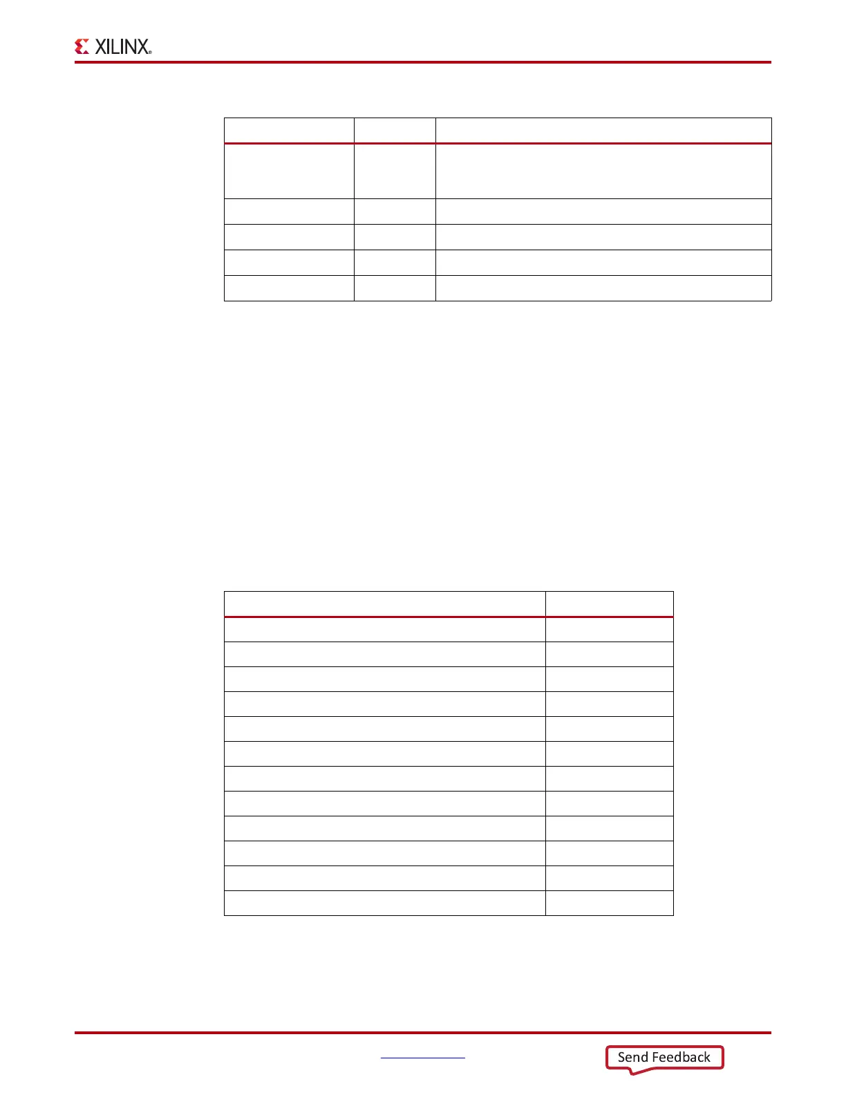
• 4 x 4 mode – This mode configures the FIFO to have 12 4-bit wide data inputs (D) and
12 4-bit wide data outputs (Q). The D0[3:0] – D9[3:0] ports map to the Q0[3:0] –
Q9[3:0] ports. D5[7:4] and D6[7:4] are the two extra data input ports that serve as D10
and D11 and map to the Q5[7:4] and Q6[7:4] output ports. The other D[7:4] ports are
not used. Table 3-16 shows the 4 x 4 mode mapping in detail.
• 8 x 4 mode – This mode configures the FIFO to have 10 8-bit wide data inputs (D) and
10 4-bit wide data outputs (Q). In 8 x 4 mode, a 2:1 multiplexer in the output datapath
serializes the 8-bit input data to the 4-bit output data width. 4 x 8 mode is generally
Q5[7:4], Q6[7:4]
O
Supplemental data out ports Q10 and Q11. Used only in 4x4
mode. Data on these ports is sourced from corresponding
input ports D5[7:4] and D6[7:4].
EMPTY
O
Empty flag. Synchronized to RDCLK.
FULL
O
Full flag. Synchronized to WRCLK.
ALMOSTEMPTY
(1)
O
Programmable level empty flag. Synchronized to RDCLK.
ALMOSTFULL
(1)
O
Programmable level full flag. Synchronized to WRCLK.
Notes:
1. The corresponding attribute can be set to a value of 1 or 2 (see Table 3-19, page 181). Accordingly, at
least one or two reads or writes occur after the flag asserts. Due to the asynchronous nature of the FIFO,
there can be one or two additional reads or writes increasing the total reads or writes to three or four.
Table 3-15: IN_FIFO Ports (Cont’d)
Port Name Input/output Description
Table 3-16: OUT_FIFO Input to Output Data Mapping in 4 x 4 Mode
Mapping Not Used
D0[3:0] → Q0[3:0] Q0[7:4]
D1[3:0] → Q1[3:0] Q1[7:4]
D2[3:0] → Q2[3:0] Q2[7:4]
D3[3:0] → Q3[3:0] Q3[7:4]
D4[3:0] → Q4[3:0] Q4[7:4]
D5[3:0] → Q4[3:0]
D6[3:0] → Q6[3:0]
D7[3:0] → Q7[3:0] Q7[7:4]
D8[3:0] → Q8[3:0] Q8[7:4]
D9[3:0] → Q9[3:0] Q9[7:4]
D10[7:4] is D5[7:4] → Q5[7:4]
D11[7:4] is D6[7:4] → Q6[7:4]