7 Series FPGAs SelectIO Resources User Guide www.xilinx.com 175
UG471 (v1.10) May 8, 2018
IO_FIFO Overview
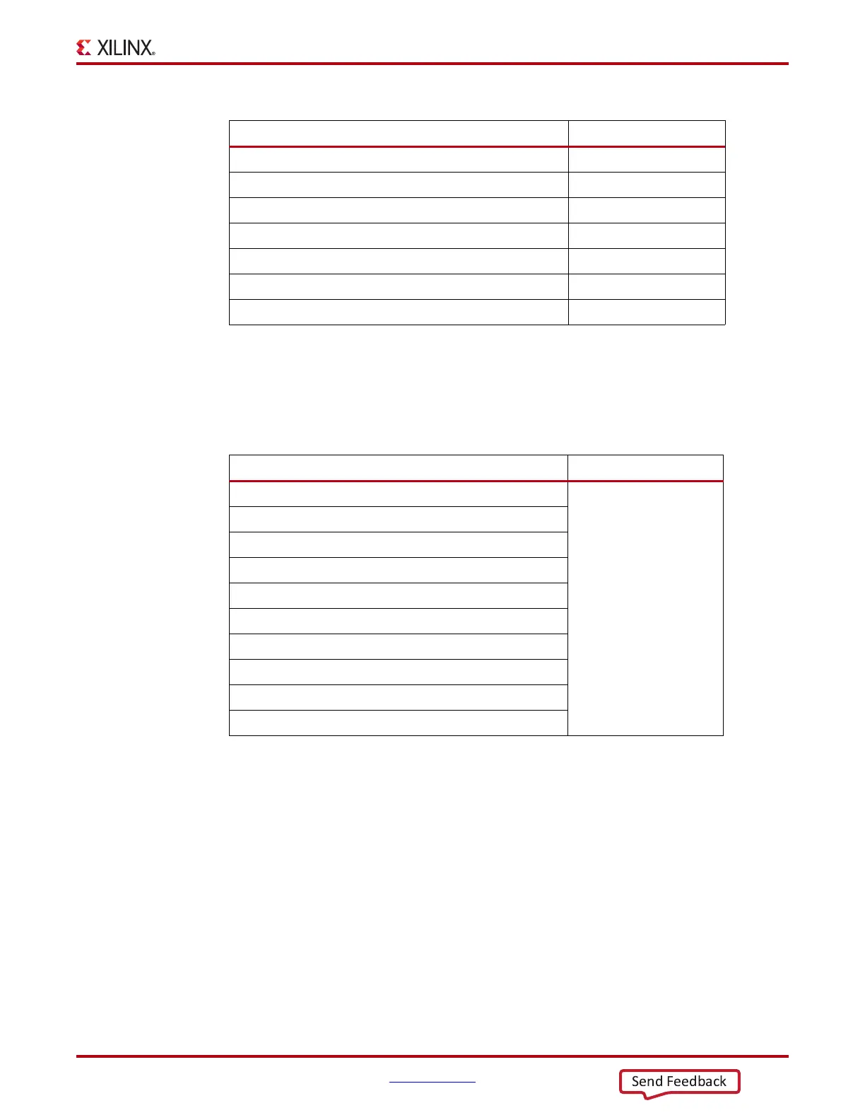
• 4 x 8 mode – This mode configures the FIFO to have 10 4-bit wide data inputs (D) and
10 8-bit wide data outputs (Q). In 4 x 8 mode, the 4-bit input data is demultiplexed to
form the 8-bit output data width. 4 x 8 mode is generally used when the output clock
frequency is greater than one half the input clock frequency and thus output data is
twice the width of the input data. Table 3-14 shows the 4 x 8 mode mapping in detail.
Both modes support the FULL, EMPTY, ALMOSTFULL, and ALMOSTEMPTY flags.
IN_FIFO Primitive
The IN_FIFO primitive is shown in Figure 3-20.
D5[3:0] → Q5[3:0]
D6[3:0] → Q6[3:0]
D7[3:0] → Q7[3:0] Q7[7:4]
D8[3:0] → Q8[3:0] Q8[7:4]
D9[3:0] → Q9[3:0] Q9[7:4]
D10[3:0] is D5[7:4] → Q5[7:4]
D11[3:0] is D6[7:4] → Q6[7:4]
Table 3-14: IN_FIFO Input to Output Data Mapping in 4 x 8 Mode
Mapping Not Used
D0[3:0] → Q0[7:0]
D1[3:0] → Q1[7:0]
D2[3:0] → Q2[7:0]
D3[3:0] → Q3[7:0]
D4[3:0] → Q4[7:0]
D5[3:0] → Q5[7:0]
D6[3:0] → Q6[7:0]
D7[3:0] → Q7[7:0]
D8[3:0] → Q8[7:0]
D9[3:0] → Q9[7:0]
Table 3-13: IN_FIFO Input to Output Data Mapping in 4 x 4 Mode (Cont’d)
Mapping Not Used