CHASSIS
3-24
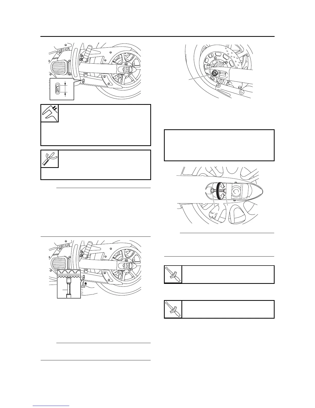
NOTE:
• The level marks of the level window on the low-
er drive belt cover are in units of 5 mm (0.20 in).
Use them as a standard for measuring the
drive belt slack.
• Measure the drive belt slack when the drive
belt has been pushed with 4.5 kg (10 lb) of
pressure using a belt tension gauge “1”.
3. Remove:
• Muffler
Refer to “ENGINE REMOVAL” on page 5-1.
4. Adjust:
• Drive belt slack
▼▼▼▼▼▼▼▼▼ ▼ ▼▼▼▼▼▼▼▼▼ ▼ ▼▼▼▼ ▼ ▼▼▼▼ ▼▼▼
NOTE:
Place the vehicle on a suitable stand so that the
rear wheel is elevated.
a. Loosen the rear wheel axle nut “1”.
b. Loosen both locknuts “2”.
c. Turn both adjusting bolts “3” in direction “a” or
“b” until the specified drive belt slack is ob-
tained.
NOTE:
Using the alignment marks on each side of the
swingarm, make sure that both belt pullers are in
the same position for proper wheel alignment.
d. Tighten the locknuts to specification.
e. Tighten the rear wheel axle nut to specifica-
tion.
▲▲▲▲▲▲▲▲▲ ▲ ▲▲▲▲ ▲ ▲▲▲▲ ▲ ▲▲▲▲ ▲ ▲▲▲▲ ▲▲▲
5. Install:
• Muffler
Refer to “ENGINE REMOVAL” on page 5-1.
Drive belt slack (on the side-
stand)
5.0–7.0 mm (0.20–0.28 in)
Drive belt slack (on a suitable
stand)
4.0–6.0 mm (0.16–0.24 in)
Belt tension gauge
90890-03170
Rear drive belt tension gauge
YM-03170
a
68
10
12
14
1
Direction “a”
Drive belt is tightened.
Direction “b”
Drive belt is loosened.
T
R
.
.
Locknut
16 Nm (1.6 m·kg, 11 ft·lb)
T
R
.
.
Rear wheel axle nut
150 Nm (15.0 m·kg, 110 ft·lb)
1
3
2
b
a