ELECTRICAL COMPONENTS
8-93
b. Turn the main switch to “ON”.
c. Measure the turn signal relay output voltage.
▲▲▲▲▲▲▲▲▲ ▲ ▲▲▲▲▲▲▲▲▲ ▲ ▲▲▲▲ ▲ ▲▲▲▲ ▲▲▲
EAS28050
CHECKING THE DIODES
Relay unit (diode)
1. Check:
• Relay unit (diode)
Out of specification → Replace.
NOTE:
The pocket tester or the analog pocket tester
readings are shown in the following table.
▼▼▼▼▼▼▼▼▼ ▼ ▼▼▼▼ ▼ ▼▼▼▼ ▼ ▼▼▼▼ ▼ ▼▼▼▼ ▼▼▼
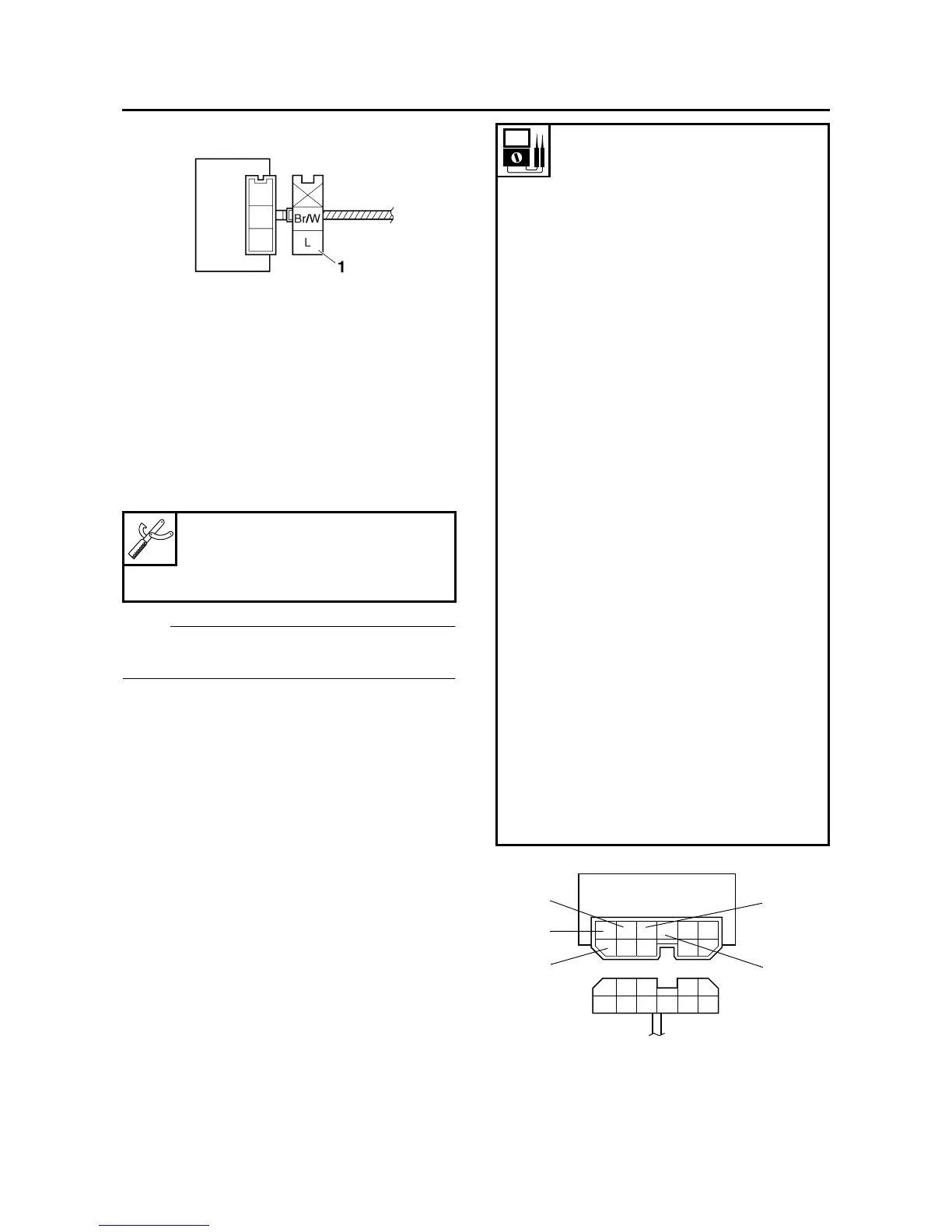
a. Disconnect the relay unit from the wire har-
ness.
b. Connect the pocket tester (Ω × 1) to the relay
unit terminals as shown.
Pocket tester
90890-03112
Analog pocket tester
YU-03112-C
Continuity
Positive tester probe → sky blue
“1”
Negative tester probe →
black/yellow “2”
No continuity
Positive tester probe →
black/yellow “2”
Negative tester probe → sky
blue “1”
Continuity
Positive tester probe → sky blue
“1”
Negative tester probe →
blue/yellow “3”
No continuity
Positive tester probe →
blue/yellow “3”
Negative tester probe → sky
blue “1”
Continuity
Positive tester probe → sky blue
“1”
Negative tester probe → sky
blue/white “4”
No continuity
Positive tester probe → sky
blue/white “4”
Negative tester probe → sky
blue “1”
Continuity
Positive tester probe →
blue/green “5”
Negative tester probe →
blue/yellow “3”
No continuity
Positive tester probe →
blue/yellow “3”
Negative tester probe →
blue/green “5”
L/G
L/Y
Sb
B/Y
Sb/W
L/W
R/LL/R
R
L
/
W
L
4
5
1
2
3