ELECTRICAL COMPONENTS
8-99
▼▼▼▼▼▼▼▼▼ ▼ ▼▼▼▼▼▼▼▼▼ ▼ ▼▼▼▼ ▼ ▼▼▼▼ ▼▼▼
a. Connect the pocket tester (Ω × 100) to the oil
level switch terminal as shown.
b. Measure the oil level switch resistance.
▲▲▲▲▲▲▲▲▲ ▲ ▲▲▲▲▲▲▲▲▲ ▲ ▲▲▲▲ ▲ ▲▲▲▲ ▲▲▲
EAS3D81013
CHECKING THE FUEL SENDER
1. Disconnect:
• Fuel sender coupler
(from the wire harness)
2. Remove:
• Fuel sender
(from the fuel tank)
3. Check:
• Fuel sender resistance
Out of specification → Replace the fuel send-
er.
▼▼▼▼▼▼▼▼▼ ▼ ▼▼▼▼▼▼▼▼▼ ▼ ▼▼▼▼ ▼ ▼▼▼▼ ▼▼▼
a. Connect the pocket tester (Ω × 1) to the fuel
sender terminals as shown.
b. Measure the fuel sender resistance.
▲▲▲▲▲▲▲▲▲ ▲ ▲▲▲▲ ▲ ▲▲▲▲ ▲ ▲▲▲▲ ▲ ▲▲▲▲ ▲▲▲
EAS3D81014
CHECKING THE FUEL LEVEL WARNING
LIGHT
This model is equipped with a self-diagnosis de-
vice for the fuel level detection circuit.
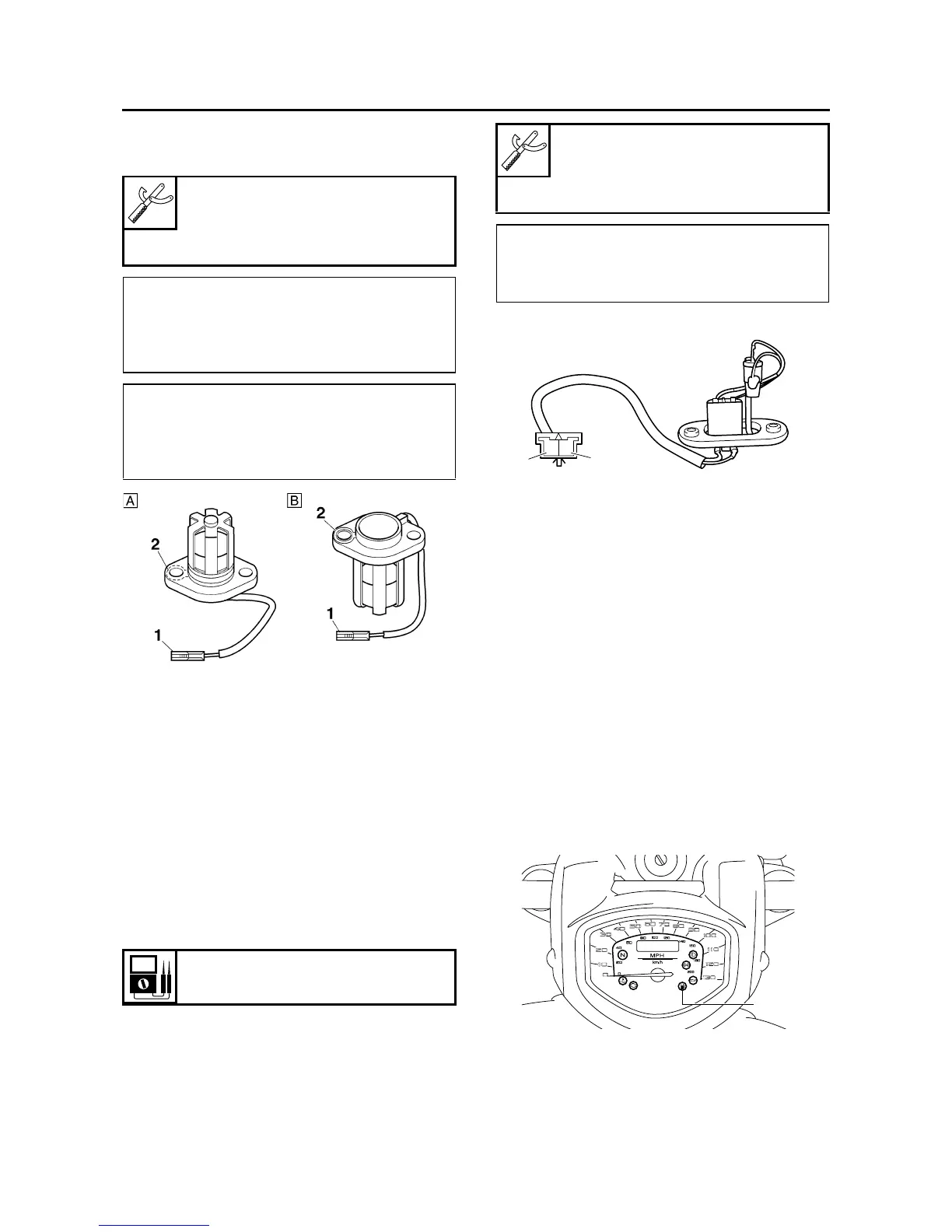
1. Check:
• Fuel level warning light “1”
(Turn the main switch to “ON”.)
Warning light comes on for a few seconds,
then goes off → Warning light is OK.
Warning light does not come on → Replace
the meter assembly.
Warning light flashes eight times, then goes
off for three seconds in a repeated cycle (mal-
function detected in fuel sender or thermistor)
→ Replace the fuel sender.
EAS3D81015
CHECKING THE OIL LEVEL WARNING
LIGHT
This model is equipped with a self-diagnosis de-
vice for the oil level detection circuit.
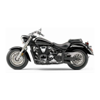
Pocket tester
90890-03112
Analog pocket tester
YU-03112-C
Minimum level position “A”
• Positive tester probe →
connector (white) “1”
• Negative tester probe →
body ground “2”
Maximum level position “B”
• Positive tester probe →
connector (white) “1”
• Negative tester probe →
body ground “2”
Fuel sender resistance
830–1720 Ω at 25 °C (77 °F)
Pocket tester
90890-03112
Analog pocket tester
YU-03112-C
• Positive tester probe →
green “1”
• Negative tester probe →
black “2”
1
2
GB
1