ENGINE
3-3
EAS20470
ENGINE
EAS20530
ADJUSTING THE VALVE CLEARANCE
The following procedure applies to all of the
valves.
NOTE:
• Valve clearance adjustment should be made
on a cold engine, at room temperature.
• When the valve clearance is to be measured or
adjusted, the piston must be at top dead center
(TDC) on the compression stroke.
1. Remove:
• Rider seat
• Left side cover
Refer to “GENERAL CHASSIS” on page 4-1.
• Fuel tank
Refer to “FUEL TANK” on page 7-1.
• Front cylinder left cover
• Front cylinder right cover
• Rear cylinder left cover
• Rear cylinder right cover
Refer to “ENGINE REMOVAL” on page 5-1.
2. Remove:
• Throttle body
• Intake manifold assembly
Refer to “THROTTLE BODIES” on page 7-6.
3. Drain:
• Coolant
Refer to “CHANGING THE COOLANT” on
page 3-16.
4. Remove:
• Front cylinder thermostat inlet hose
• Rear cylinder thermostat inlet hose
Refer to “THERMOSTAT” on page 6-4.
5. Disconnect:
• Spark plug caps
Refer to “ENGINE REMOVAL” on page 5-1.
6. Remove:
• Spark plugs
Refer to “CAMSHAFTS” on page 5-11.
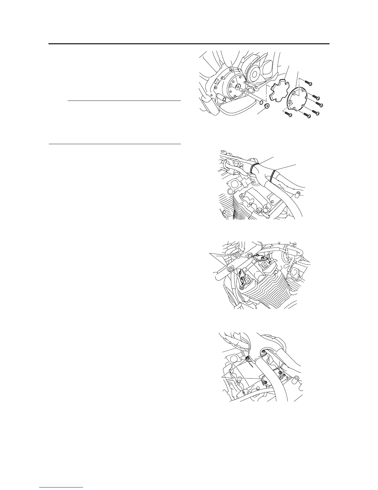
7. Remove:
• Damper cover “1”
• Damper “2”
• Timing mark accessing screw “3”
• Crankshaft end screw “4”
8. Remove:
• Plastic locking tie “1”
• Plastic locking tie “2”
9. Remove:
• Front cylinder tappet covers “1”
10.Remove:
• Rear cylinder tappet covers “1”
11.Measure:
• Valve clearance
Out of specification → Adjust.
4
1
2
3
1
2
1
1





 To Next Page