ELECTRICAL COMPONENTS
8-97
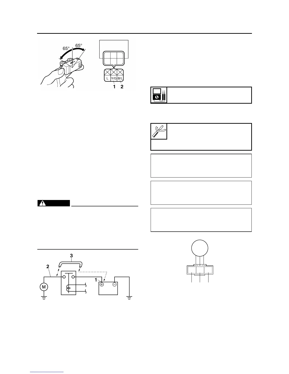
c. Turn the main switch to “ON”.
d. Tilt the lean angle sensor 65°.
e. Measure the lean angle sensor output volt-
age.
▲▲▲▲▲▲▲▲▲ ▲ ▲▲▲▲▲▲▲▲▲ ▲ ▲▲▲▲ ▲ ▲▲▲▲ ▲▲▲
EAS3D81011
CHECKING THE STARTER MOTOR
OPERATION
1. Check:
• Starter motor operation
Does not operate → Perform the electric
starting system troubleshooting, starting with
step 4.
Refer to “TROUBLESHOOTING” on page
8-11.
▼▼▼▼▼▼▼▼▼ ▼ ▼▼▼▼▼▼▼▼▼ ▼ ▼▼▼▼ ▼ ▼▼▼▼ ▼▼▼
a. Connect the positive battery terminal “1” and
starter motor lead “2” with a jumper lead “3”.
WARNING
EWA13810
• A wire that is used as a jumper lead must
have at least the same capacity of the bat-
tery lead, otherwise the jumper lead may
burn.
• This check is likely to produce sparks,
therefore, make sure no flammable gas or
fluid is in the vicinity.
b. Check the starter motor operation.
▲▲▲▲▲▲▲▲▲ ▲ ▲▲▲▲▲▲▲▲▲ ▲ ▲▲▲▲ ▲ ▲▲▲▲ ▲▲▲
EAS28150
CHECKING THE STATOR COIL
1. Disconnect:
• Stator coil coupler
(from the wire harness)
2. Check:
• Stator coil resistance
Out of specification → Replace the crank-
shaft position sensor/stator assembly.
▼▼▼▼▼▼▼▼▼ ▼ ▼▼▼▼ ▼ ▼▼▼▼ ▼ ▼▼▼▼ ▼ ▼▼▼▼ ▼▼▼
a. Connect the pocket tester (Ω × 1) to the stator
coil coupler as shown.
b. Measure the stator coil resistance.
▲▲▲▲▲▲▲▲▲ ▲ ▲▲▲▲ ▲ ▲▲▲▲ ▲ ▲▲▲▲ ▲ ▲▲▲▲ ▲▲▲
EAS28170
CHECKING THE RECTIFIER/REGULATOR
1. Check:
• Charging voltage
Out of specification → Replace the rectifi-
er/regulator.
Stator coil resistance
0.112–0.168 Ω
Pocket tester
90890-03112
Analog pocket tester
YU-03112-C
• Positive tester probe →
white “1”
• Negative tester probe →
white “2”
• Positive tester probe →
white “1”
• Negative tester probe →
white “3”
• Positive tester probe →
white “2”
• Negative tester probe →
white “3”
2
3
1
WWW