FUEL INJECTION SYSTEM
8-38
Communication error with the meter
EAS27400
TROUBLESHOOTING METHOD
The engine operation is not normal and the
engine trouble warning light comes on.
1. Check:
• Fault code number
▼▼▼▼▼▼▼▼▼ ▼ ▼▼▼▼▼▼▼▼▼ ▼ ▼▼▼▼ ▼ ▼▼▼▼ ▼▼▼
a. Check the fault code number displayed on
the meter.
b. Identify the faulty system with the fault code.
Refer to “Self-Diagnostic Function table”.
c. Identify the probable cause of the malfunc-
tion. Refer to “Diagnostic code table”.
▲▲▲▲▲▲▲▲▲ ▲ ▲▲▲▲▲▲▲▲▲ ▲ ▲▲▲▲ ▲ ▲▲▲▲ ▲▲▲
2. Check and repair the probable cause of the
malfunction.
3. Perform the ECU reinstatement action.
Refer to “Reinstatement method” in the table
in “TROUBLESHOOTING DETAILS”.
4. Turn the main switch to “OFF” and back to
“ON”, and then check that no fault code num-
ber is displayed.
NOTE:
If fault codes are displayed, repeat steps (1) to
(4) until no fault code number is displayed.
5. Erase the malfunction history in the diagnos-
tic mode. Refer to “Sensor operation table
(Diagnostic code No. 62)”.
NOTE:
Turning the main switch to “OFF” will not erase
the malfunction history.
The engine operation is not normal, but the
engine trouble warning light does not come
on.
1. Check the operation of the following sensors
and actuators in the diagnostic mode. Refer
to “Sensor operation table” and “Actuator op-
eration table”.
If a malfunction is detected in the sensors or
actuators, repair or replace all faulty parts.
If no malfunction is detected in the sensors
and actuators, check and repair the inner
parts of the engine.
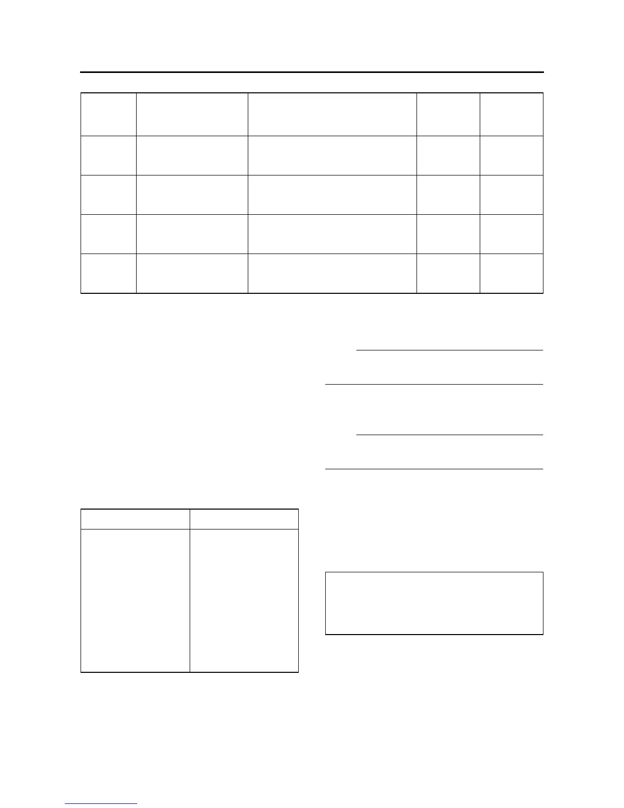
Fault
code No.
Item Symptom
Able / un-
able to start
Able / un-
able to
drive
Er-1
ECU internal malfunc-
tion
(output signal error)
No signals are received from the
ECU.
Unable Unable
Er-2
ECU internal malfunc-
tion
(output signal error)
No signals are received from the
ECU within the specified duration.
Unable Unable
Er-3
ECU internal malfunc-
tion
(output signal error)
Data from the ECU cannot be re-
ceived correctly.
Unable Unable
Er-4
ECU internal malfunc-
tion
(input signal error)
Non-registered data has been re-
ceived from the meter.
Unable Unable
Fault code No. No fault code No.
Check and repair.
Refer to “TROUBLE-
SHOOTING DE-
TAI LS” on page 8-45.
Monitor the opera-
tion of the sensors
and actuators in the
diagnostic mode. Re-
fer to “Sensor opera-
tion table” and
“Actuator operation
table”.
Check and repair.
Refer to “Self-Diag-
nostic Function ta-
ble”.
01: Throttle position sensor (throttle angle)
30: Front cylinder ignition coil
31: Rear cylinder ignition coil
36: Front cylinder injector
37: Rear cylinder injector