ELECTRICAL COMPONENTS
8-101
▼▼▼▼▼▼▼▼▼ ▼ ▼▼▼▼▼▼▼▼▼ ▼ ▼▼▼▼ ▼ ▼▼▼▼ ▼▼▼
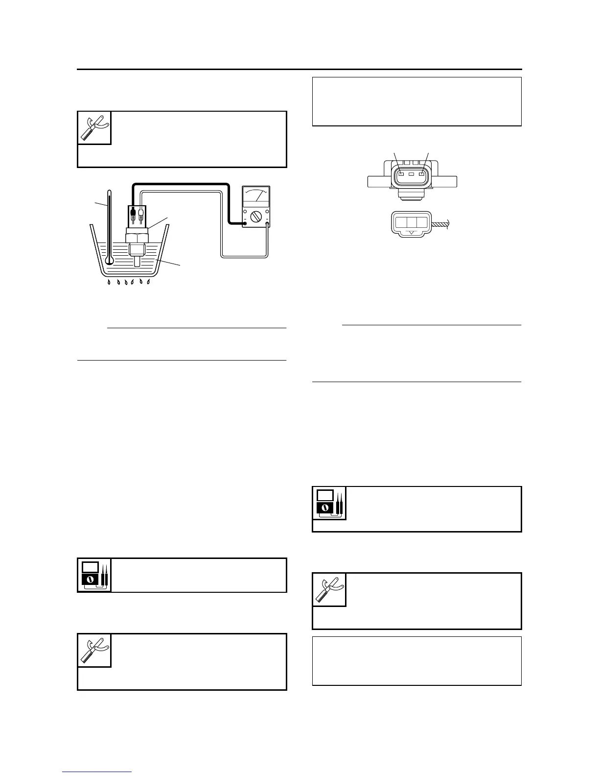
a. Connect the pocket tester (Ω × 100) to the
coolant temperature sensor as shown.
b. Immerse the coolant temperature sensor “1”
in a container filled with coolant “2”.
NOTE:
Make sure the coolant temperature sensor ter-
minals do not get wet.
c. Place a thermometer “3” in the coolant.
d. Slowly heat the coolant, and then let it cool
down to the specified temperature.
e. Measure the coolant temperature sensor re-
sistance.
▲▲▲▲▲▲▲▲▲ ▲ ▲▲▲▲▲▲▲▲▲ ▲ ▲▲▲▲ ▲ ▲▲▲▲ ▲▲▲
EAS28300
CHECKING THE THROTTLE POSITION
SENSOR
1. Remove:
• Throttle position sensor
(from the throttle body)
2. Check:
• Throttle position sensor maximum resistance
Out of specification → Replace the throttle
position sensor.
▼▼▼▼▼▼▼▼▼ ▼ ▼▼▼▼▼▼▼▼▼ ▼ ▼▼▼▼ ▼ ▼▼▼▼ ▼▼▼
a. Connect the pocket tester (Ω × 1k) to the
throttle position sensor terminals as shown.
b. Measure the throttle position sensor maxi-
mum resistance.
▲▲▲▲▲▲▲▲▲ ▲ ▲▲▲▲ ▲ ▲▲▲▲ ▲ ▲▲▲▲ ▲ ▲▲▲▲ ▲▲▲
3. Install:
• Throttle position sensor
NOTE:
When installing the throttle position sensor, ad-
just its angle properly. Refer to “ADJUSTING
THE THROTTLE POSITION SENSOR” on page
7-9.
EAS28410
CHECKING THE INTAKE AIR PRESSURE
SENSORS
The following procedure applies to both of the in-
take air pressure sensors.
1. Check:
• Intake air pressure sensor output voltage
Out of specification → Replace.
▼▼▼▼▼▼▼▼▼ ▼ ▼▼▼▼ ▼ ▼▼▼▼ ▼ ▼▼▼▼ ▼ ▼▼▼▼ ▼▼▼
a. Connect the pocket tester (DC 20 V) to the in-
take air pressure sensor coupler as shown.
Pocket tester
90890-03112
Analog pocket tester
YU-03112-C
Resistance
4.0–6.0 kΩ
Pocket tester
90890-03112
Analog pocket tester
YU-03112-C
3
1
2
• Positive tester probe →
blue “1”
• Negative tester probe →
black/blue “2”
Intake air pressure sensor output
voltage
3.75–4.25 V
Pocket tester
90890-03112
Analog pocket tester
YU-03112-C
• Positive tester probe →
pink “1” or pink/white
• Negative tester probe →
black/blue “2”
L
Y
B/L
21