CRANKSHAFT
5-78
4. Tighten:
• Connecting rod nuts
▼▼▼▼▼▼▼▼▼ ▼ ▼▼▼▼▼▼▼▼▼ ▼ ▼▼▼▼ ▼ ▼▼▼▼ ▼▼▼
WARNING
EWA3D81005
• Replace the connecting rod bolts and nuts
with new ones.
• Clean the connecting rod bolts.
NOTE:
Tighten the connecting rod bolts using the fol-
lowing procedure.
a. Tighten the connecting rod bolts to specifica-
tion with a torque wrench.
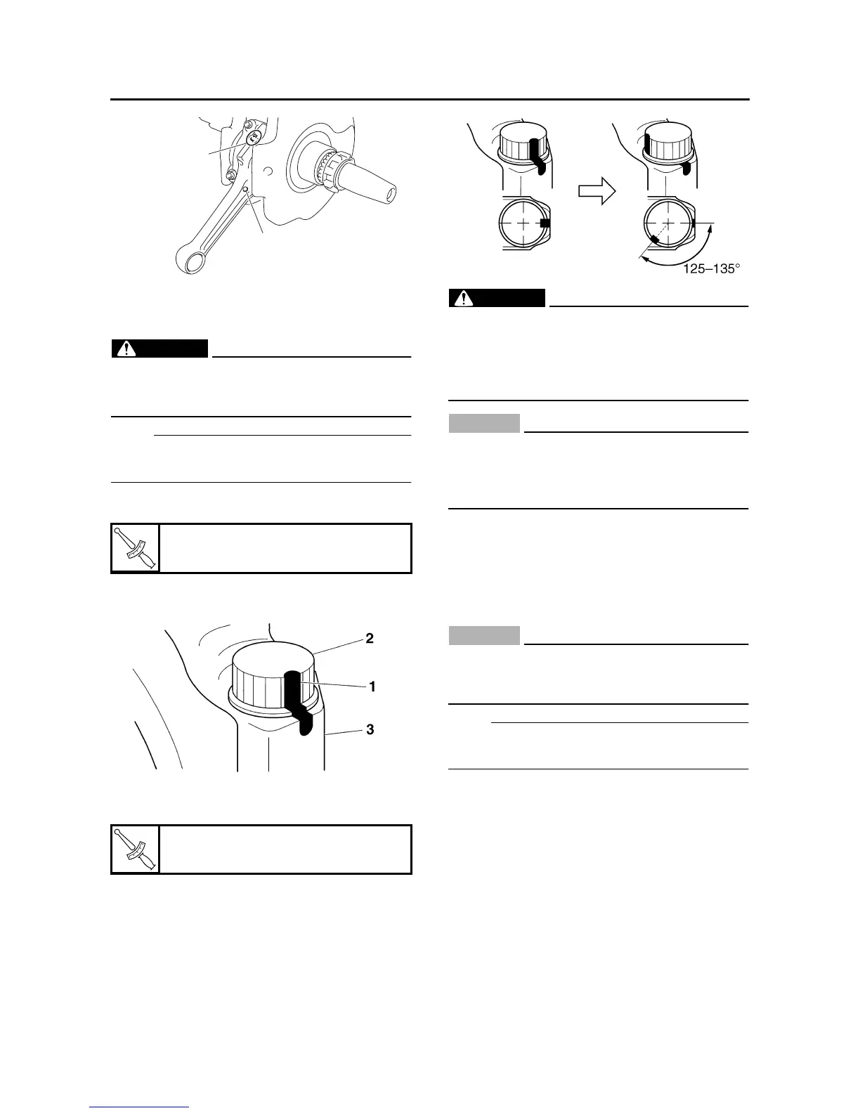
b. Put a mark “1” on the corner of the connecting
rod bolt “2” and the connecting rod cap “3”.
c. Tighten the connecting rod bolts further to
reach the specified angle 125–135°.
WARNING
EWA3D81006
When a bolt is tightened more than the spec-
ified angle, do not loosen and then retighten
it.
Replace the bolt with a new one and perform
the procedure again.
CAUTION:
ECA3D81012
• Do not use a torque wrench to tighten the
bolt to the specified angle.
• Tighten the bolt until it is at the specified
angle.
▲▲▲▲▲▲▲▲▲ ▲ ▲▲▲▲ ▲ ▲▲▲▲ ▲ ▲▲▲▲ ▲ ▲▲▲▲ ▲▲▲
EAS26210
INSTALLING THE CRANKSHAFT
ASSEMBLY
1. Install:
• Crankshaft assembly
CAUTION:
ECA3D81013
To avoid scratching the crankshaft and to
ease the installation procedure, lubricate
each bearing with engine oil.
NOTE:
Align the right connecting rod with the rear cylin-
der sleeve hole.
T
R
.
.
Connecting rod bolt (1st)
15 Nm (1.5 m·kg, 11 ft·lb)
T
R
.
.
Connecting rod bolt (final)
Specified angle 125–135°
c
d