CRANKSHAFT
5-76
NOTE:
• Do not move the connecting rod or crankshaft
until the clearance measurement has been
completed.
• Lubricate the bolts threads and nut seats with
molybdenum disulfide grease.
• Make sure the projection “c” on the connecting
rod faces towards the left side of the crank-
shaft.
• Make sure the characters “d” on both the con-
necting rod and connecting rod cap are
aligned.
e. Tighten the connecting rod bolts.
Refer to “INSTALLING THE CONNECTING
RODS” on page 5-77.
f. Remove the connecting rod and big end
bearings.
Refer to “REMOVING THE CONNECTING
RODS” on page 5-75.
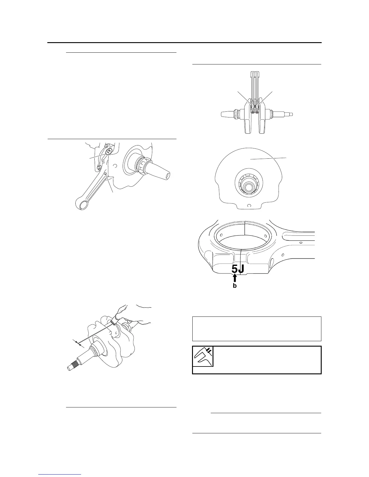
g. Measure the compressed Plastigauge®
width “e” on the crankshaft pin.
If the crankshaft-pin-to-big-end-bearing
clearance is out of specification, select re-
placement big end bearings.
▲▲▲▲▲▲▲▲▲ ▲ ▲▲▲▲▲▲▲▲▲ ▲ ▲▲▲▲ ▲ ▲▲▲▲ ▲▲▲
4. Select:
• Big end bearings (P
1
–P
2
)
NOTE:
• The numbers “a” stamped into the crankshaft
web and the numbers “b” on the connecting
rods are used to determine the replacement
big end bearing sizes.
• P
1
–P
2
refer to the bearings shown in the crank-
shaft illustration.
For example, if the connecting rod P
1
and the
crankshaft web P numbers are 5 and 1 re-
spectively, then the bearing size for P
1
is:
5. Measure:
• Crankshaft journal diameter “a”
Out of specification → Replace the crank-
shaft.
NOTE:
Measure the diameter of each crankshaft journal
at two places.
c
d
e
P
1
(connecting rod) - P (crankshaft)
=
5 - 1 = 4 (green)
Bearing color code
1.Blue 2.Black 3.Brown 4.Green
5.Yellow
P1
P2
a
1