MACHINING PROGRAM 4
4-45
C. Parameter setting
The main parameter of processing is described.
The table shows the standard parameter and setting set in this manual.
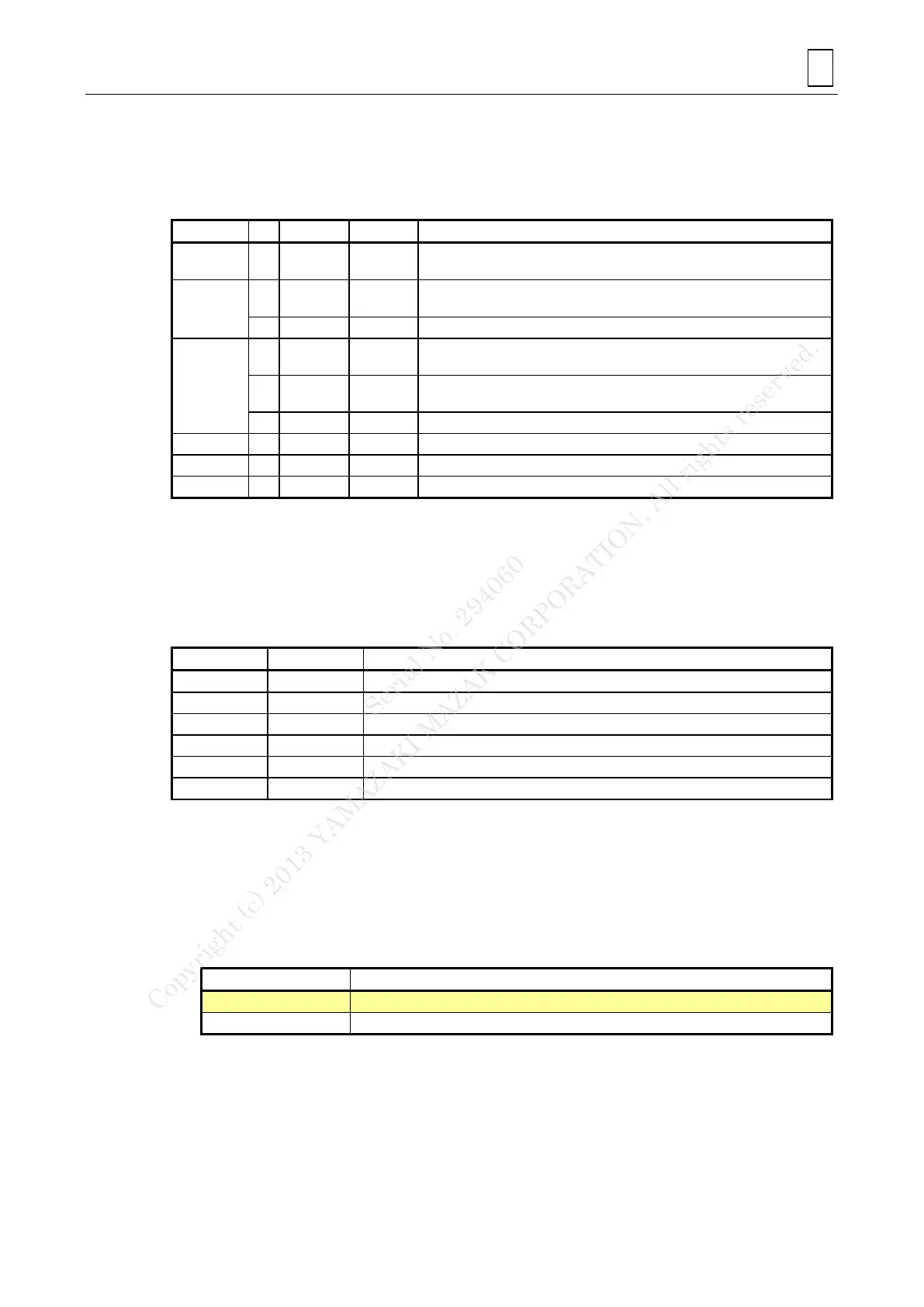
Parameter setting
High-speed smoothing control valid
(No deceleration at very slightly stepped sections)
Type of coordinate system for controlling the tool tip point
The table coordinate system
Tool tip point control scheme Joint interpolation
Override scheme for G0
The clamping speed at the machine control point
Override scheme for G1
The clamping speed at the machine control point
C-axis reference position 0 degrees
Rotational axis shape correction Valid
The axis does not move when command G49 is issued
During independent start of tool tip point control No movement
Note 1: See 4-4-5 1. C. for coordinate system for controlling the tool tip point
Note 2: See 4-4-5 1. C. for the setting the workpiece coordinate system
D. G-codes/M-codes
See the document [99 Supplement] for details.
G-codes
Tool radius compensation OFF
Tool radius compensation for five-axis machining (left)
Tool tip point control (Type 1) ON
High-accuracy mode (Geometry compensation)
Note 1: The geometry compensation reduces geometry errors caused by the delay in the
smoothing circuits and servo systems.
Note 2: The high-speed machining mode features high-speed execution of free form programs
such as die and mold machining approximated by fine increments data.
Combined with the geometrical correction function, it produces high quality surface
finish.
High-accuracy mode
Modal spline interpolation
Note 1: is G-code used by sample program.
Note 2: G61.2 is a geometry compensation with fine spline interpolation feature for a further
better quality surface for the CAM-made minute increments block by block data
operation.
Serial No. 294060
Copyright (c) 2013 YAMAZAKI MAZAK CORPORATION. All rights reserved.
 Loading...