6240B DC Voltage Current Source/Monitor Operation Manual
5.1.5 Connection with Fixture 12701A
5-7
5.1.5 Connection with Fixture 12701A
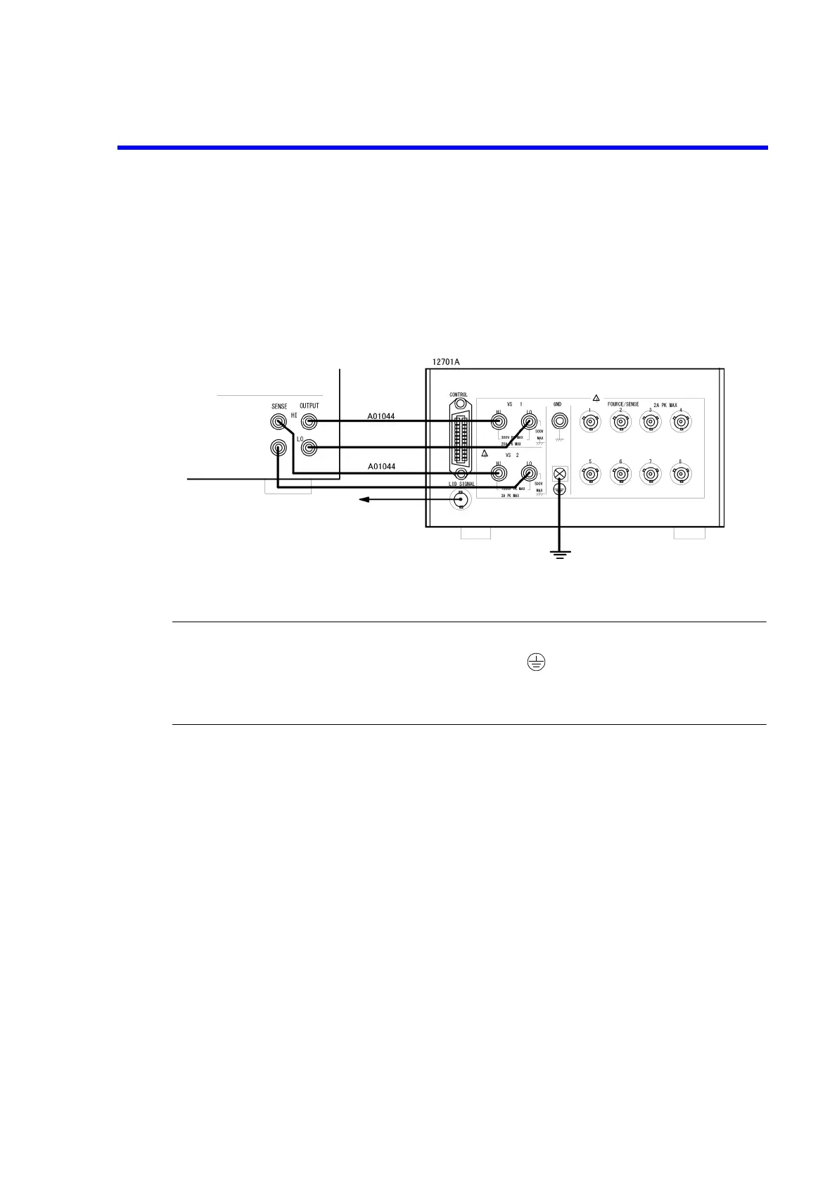
The following figure shows the connection with the 12701A.
This example uses 4-wire connection.
2-wire connection does not require the SENSE connection.
For more information on the device connection inside the 12701A, refer to 12701A Operation Manual.
Figure 5-7 Connection with 12701A
CAUTION:Follow the procedure below to prevent electric shock.
1. Be sure to ground the 12701A protective grounding terminal .
2. Connect the 12701A LID SIGNAL to the INTERLOCK terminal on the 6240B rear panel, and set the param-
eter "OPR Signal" to InterLock In.
This enables the interlock function. When the 12701A cover opens, the 6240B will be set to Standby.
To the INTERLOCK input
terminal on the rear panel
6240B

 Loading...


