6240B DC Voltage Current Source/Monitor Operation Manual
5.4 Operational Principles
5-75
5.4 Operational Principles
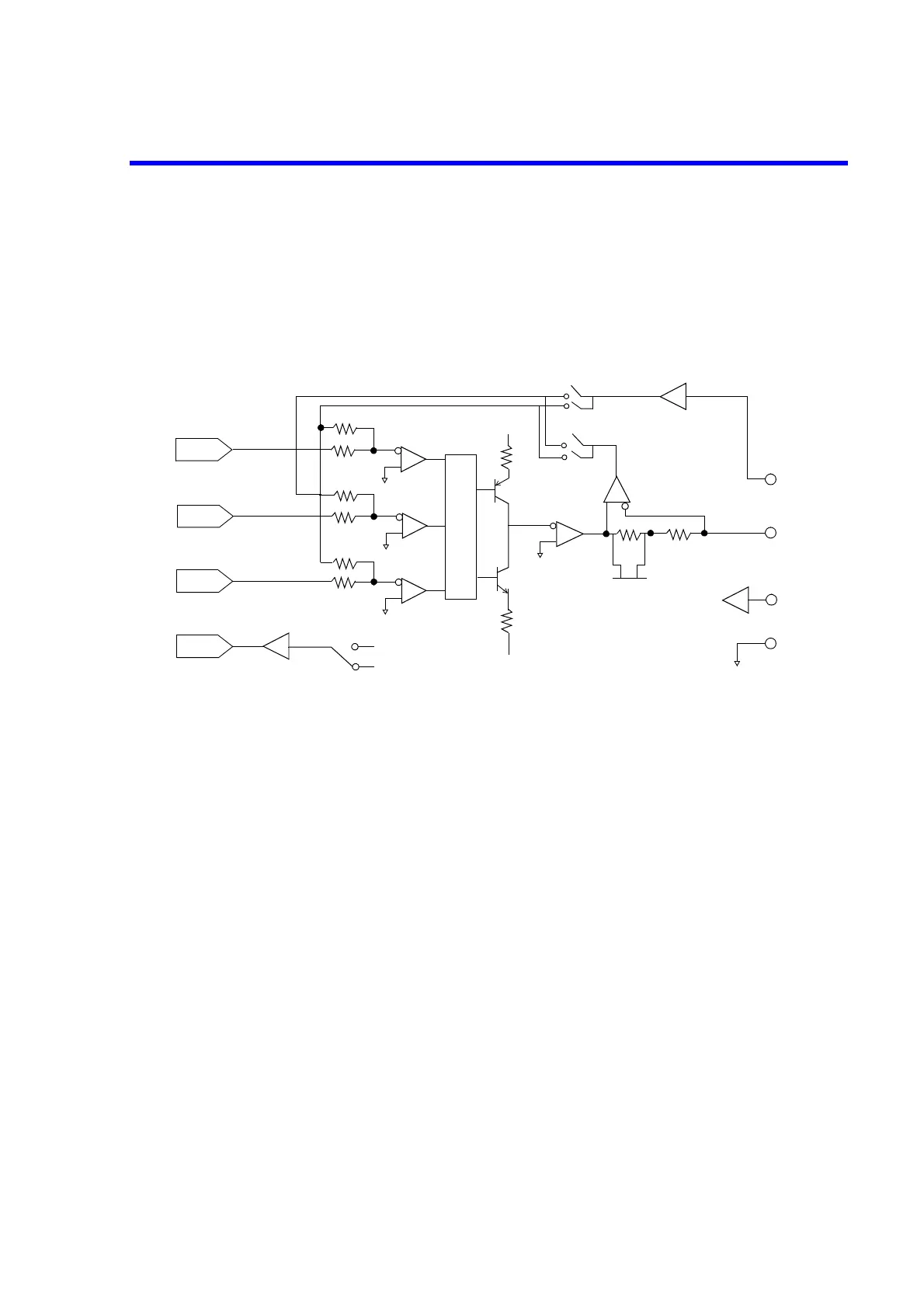
5.4.1 Block Diagram
5.4.2 Operational Principles
• The 6240B contains a DA converter SrcDAC, for setting the voltage source or current source. It also
has DA converters, HiLimitDAC and LoLimitDAC for setting the current limiters and the voltage
limiters.
The SrcDAC has 16-bit conversion accuracy, and the HiLimitDAC and the LoLimitDAC have
13-bit conversion accuracy.
The output from the DA converters is input to three error amplifiers, Src (A1), HiLmt (A2), and
LoLmt (A3) respectively.
• For voltage source, the SrcDAC becomes a voltage-source DAC, and the Src error amplifier (A1)
becomes a voltage-source error amplifier.
Also, HiLimitDAC becomes a DAC for current limiter on the HI side and the HiLmt error amplifier
(A2) becomes an error amplifier for current limiter on the HI side.
Likewise, the LoLimitDAC and the LoLmt error amplifier (A3) work as current limiter on the LO
side.
At this time, 0 is ON for SW1 in the feedback circuit and 1 is ON for SW2.
For current source, the uses of each DAC and error amplifier are switched; for SW1 1 is ON and for
SW2 0 is ON to generate the current.
• Source and limiter are switched by the switching circuit shown in the above figure, comparing the
feedback amount for each, then switching to the larger one.
• Current range switching is done by switching the current detection resistor Rs. Consequently, the
current measurement always takes place in the same range as that of current source or current-lim-
iter.
HiLimit
DAC
Src
DAC
LoLimit
DAC
ADC
A1
A2
A3
HiLmt
Src
LoLmt
A4
RS2
A6
SW2
SW1
VM
IM
RS1
A5
A7
HI SENSE
HI OUTPUT
LO SENSE
LO OUTPUT
A9
SW3
VM
IM
0
1
0
1
Switching circuit

 Loading...

