6240B DC Voltage Current Source/Monitor Operation Manual
5.1.2 Remote Sensing (2-Wire/4-Wire Connection)
5-2
5.1.2 Remote Sensing (2-Wire/4-Wire Connection)
When connecting the 6240B and the DUT, use 2-wire or 4-wire connection while considering the follow-
ing conditions:
• Apply 2-wire connection if the output current is relatively low and the cable line resistance does not
matter.
• Apply 4-wire connection if the output current is relatively high and the cable line resistance matters.
• When using within the specified accuracy:
(Line resistance output current) 10 V 2-wire connection
(Line resistance output current) > 10 V 4-wire connection
The line resistance of the supplied cable A01044 is approximately 100 m.
Thus, when the output current is 100 A or higher, use the 4-wire connection.
• When allowing the error voltage (ev):
(Line resistance output current) ev 2-wire connection
(Line resistance output current) > ev 4-wire connection
When the supplied cable A01044 is used and the error voltage of 10 mV is allowed, the 2-wire con-
nection is used up to 100 mA.
Pressing the 4W/2W key switches between the 2-wire and 4-wire connections.
2-wire connection: The 2W indicator goes ON.
4-wire connection: The 4W indicator goes ON.
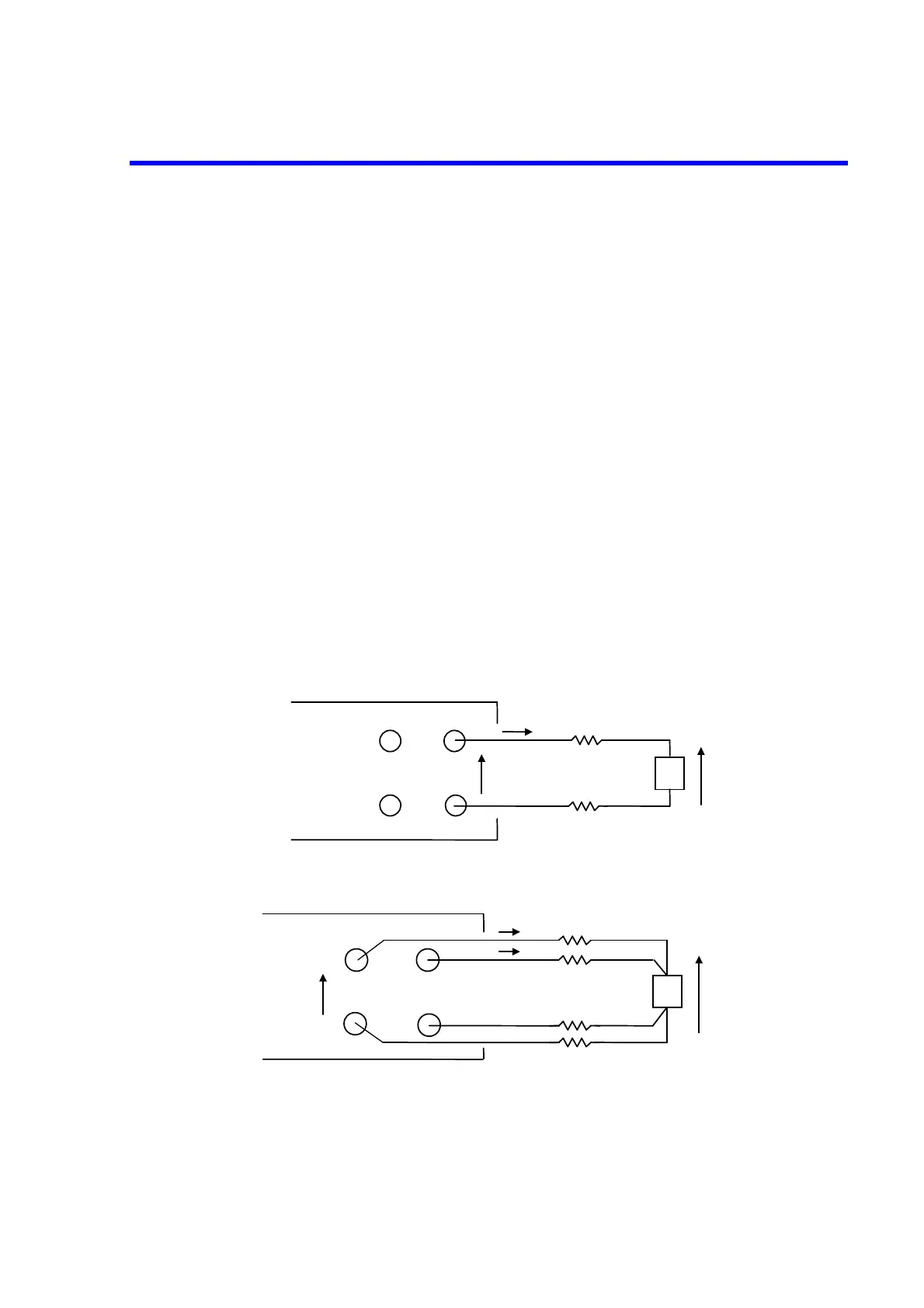
Figure 5-2 2-Wire and 4-Wire Connections
DRIVING GUARD
HI
SENSE OUTPUT
LO
Eo
r
1
r
4
DUT
Vo=Eo-(r
3
+r
4
) Is
r
3
r
2
Is
Io
Vo
≒
Eo
Vo
DRIVING GUARD
HI
SENSE OUTPUT
LO
Io
r
2
Eo
DUT
r
1
Vo
Vo=Eo-(r
1
+r
2
) Io
An error may occur due to r1 and r2 voltage drop.
(a) 2-wire connection
(b) 4-wire connection

 Loading...

