6240B DC Voltage Current Source/Monitor Operation Manual
5.2.12 Operating Multiple 6240B
5-66
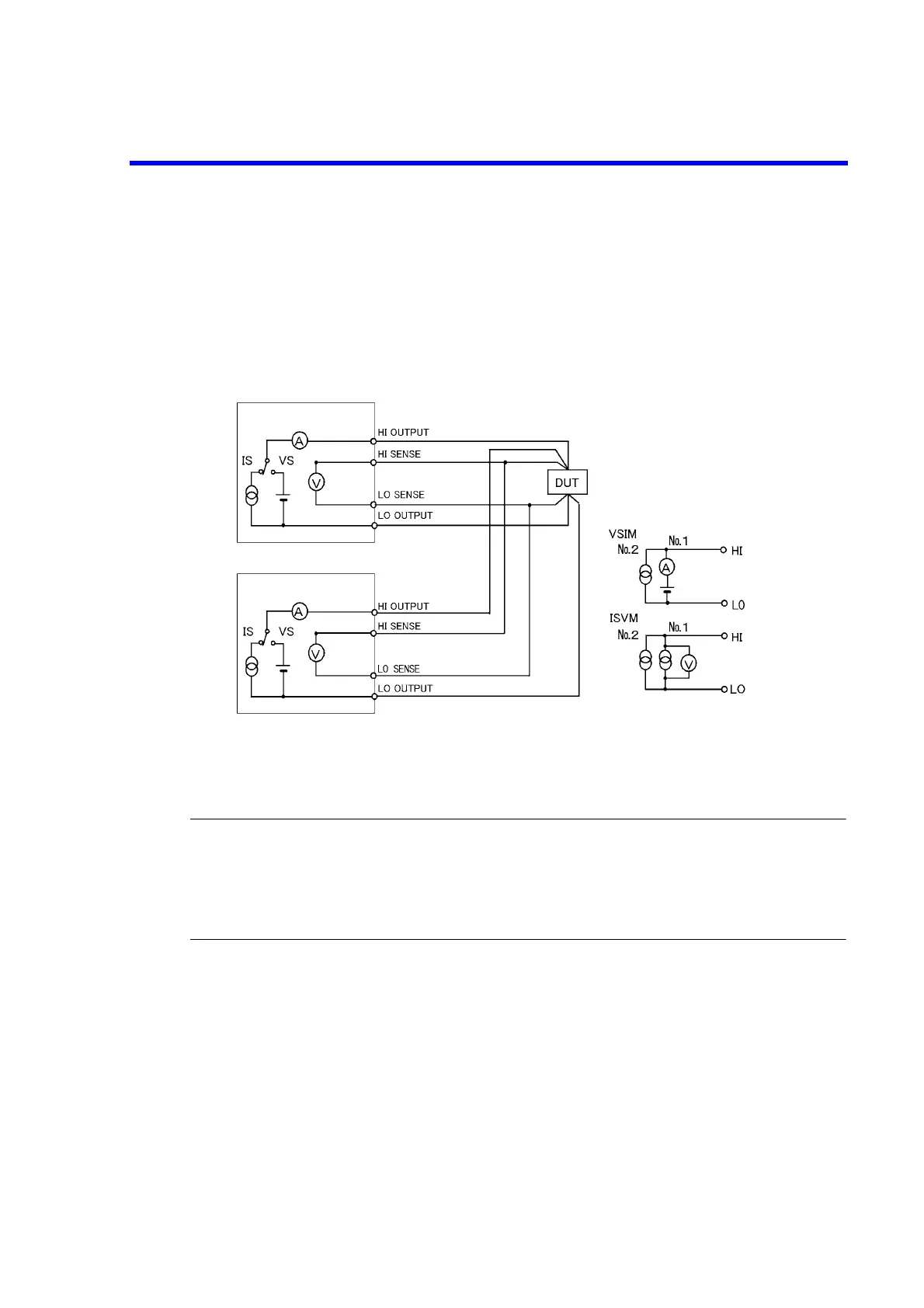
5.2.12.3 Parallel Connection
Two 6240B units connected in parallel can generate up to 2 A/15 V.
The following shows a connection diagram in which two units are connected in parallel using a 4-wire con-
nection. Two units are used for voltage measurements at two points of different timing, such as for a pulse
charge and discharge test of a battery.
Figure 5-16 Parallel Connection
CAUTION:
1. If the load is opened, the current flows from the higher to the lower of the set voltage. Depending on the set-
tings, an overload may be generated.
2. If the load is opened when three or more units are connected in parallel, which one to be used as source and
the other to be used as sink are decided by the setting voltage, and the voltage control is performed in accor-
dance with this balance.
6240B No.1
6240B No.2
Output voltage = The smaller setting voltages of No. 1 and No. 2 (for constant voltage)
Output current = No.1 setting current + No. 2 setting current (for constant current)
 Loading...


