6240B DC Voltage Current Source/Monitor Operation Manual
5.2.8 Alarm Detection
5-45
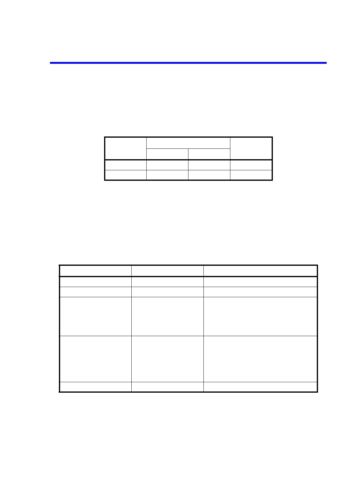
5.2.7.3 Displaying and Outputting of Limiter Detection
Three indicators, LMT, HL, and LL are used for displaying the limiter detection.
LMT indicates that measured data is obtained in the limiter detection status.
HL and LL indicate that the limiter is currently being activated.
The following table shows a relation between limiter detection display, remote output and buzzer.
5.2.8 Alarm Detection
The 6240B has a function to detect the following alarms to prevent itself and the DUT from being dam-
aged. When any of these alarms is detected, a message is displayed and output to the remote device event
status register, the error register and the header of measurement data.
The following table shows the messages and their descriptions and causes.
• When Source Unit or Fan Stop occurs, the output is set to Standby and operation is not possible until
the power is turned on again.
• When Over Heat occurs, the output is set to Standby and operation is not possible until the cause of
the error is removed.
• When Over Load occurs, the output is set to Standby.
Display
Remote output
Buzzer
Sub header Status
LMT Yes No No
HL/LL No Yes Yes
Table 5-12 Alarm Detection Contents
Message Description Cause
Source Unit Source unit malfunction Malfunction
Fan Stop Fan stopped Malfunction
Over Heat Overheat (Internal overheat) • Malfunction
• Sink operation outside the specified range
• The vents are blocked.
• Ambient temperature exceeds the speci-
fied range.
Over Load Overload • Over voltage applied from an external
device
• Connecting to an external voltage source
exceeding the voltage limiter setting
• If output sensing is 4-wire connection, LO
OUTPUT and LO SENSE may open.
LMT/HL/LL indicator Limiter activated • The voltage or current limiter is activated.

 Loading...


