6240B DC Voltage Current Source/Monitor Operation Manual
5.2.11 External Control Signals
5-58
5.2.11 External Control Signals
These signals are I/O signals for synchronizing multiple units, scanner or DMM control, and interlock and
other external controls.
The following table shows the signal names, levels and functions.
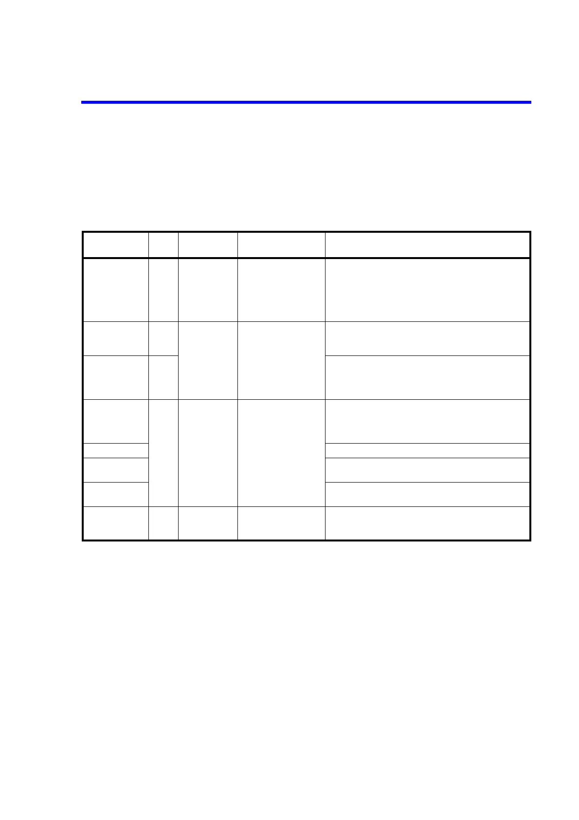
Table 5-14 External Control Signal Functions
Signal
Input/
Output
Level Impedance Function
TRIGGER IN Input TTL negative
pulse
(2 s or more)
Approx. 4.7 k • Starts measurement in the DC source mode.
• Outputs pulses in the pulse source mode.
• Starts the sweep source mode.
•Step-up
• Outputs pulses in the low-resistance measurement pulse
source mode.
COMPLETE OUT
*1
Output TTL negative
pulse
(10 s or more)
*3
Approx. 100 open drain
(Pulled up to +5 V with
10 k)
• Measurement start signal (FRONT)
• Measurement complete and period complete signal (END)
• Comparator calculation result signal (HI/GO/LO)
SYNC OUT *1 Output • Pulse output signal in the pulse source mode
• Step-up signal in the sweep source mode
• Pulse output signal in the low-resistance measurement
pulse source mode
INTERLOCK IN
*2
Input TTL negative
level
Approx. 10 k • Sets Standby when the signal level changes from LO to
HI.
• When the signal is "HI" or Open, the output cannot be
changed to Operate.
STBY IN *2 • Sets Standby when the signal level changes from LO to HI.
OPR/STBY IN
*2
• Sets Standby when the signal level changes from LO to HI.
• Sets Operate when the signal level changes from HI to LO.
OPR/SUS IN *2 • Sets Suspend when the signal level changes from LO to HI.
• Sets Operate when the signal level changes from HI to LO.
OPERATE OUT
*2
Output TTL negative
level
*3
Approx. 100 open drain
(Pulled up to +5 V with
10 k)
• Outputs LO in Operate status.
• Outputs HI in Standby or Suspend status.
*1, *2: The same terminal is used by switching respectively.
*1: The SYNC OUT signal is not output in the DC source mode.
*3: The output signal pulse width can be se to 100 s.

 Loading...

