6240B DC Voltage Current Source/Monitor Operation Manual
5.2.14 Memory Clear
5-68
NOTE:
1. In the following cases, store mode ON/OFF and storing operation changes cannot be performed.
• During auto trigger mode in the DC source, pulse source, or low-resistance measurement pulse source
mode
• During sweep operation in the sweep source mode
2. In the low-resistance measurement pulse sweep mode, the Burst mode cannot be set. When the Burst mode is
selected, switching to the low-resistance measurement pulse sweep mode will set the Normal mode.
5.2.14 Memory Clear
The memory data is cleared in the following conditions:
• When Memory Clear is executed on the menu screen
• When the RL command is executed
• When the store mode is set to ON (Normal or Burst).
• When the store mode is switched between Normal and Burst.
•Power ON
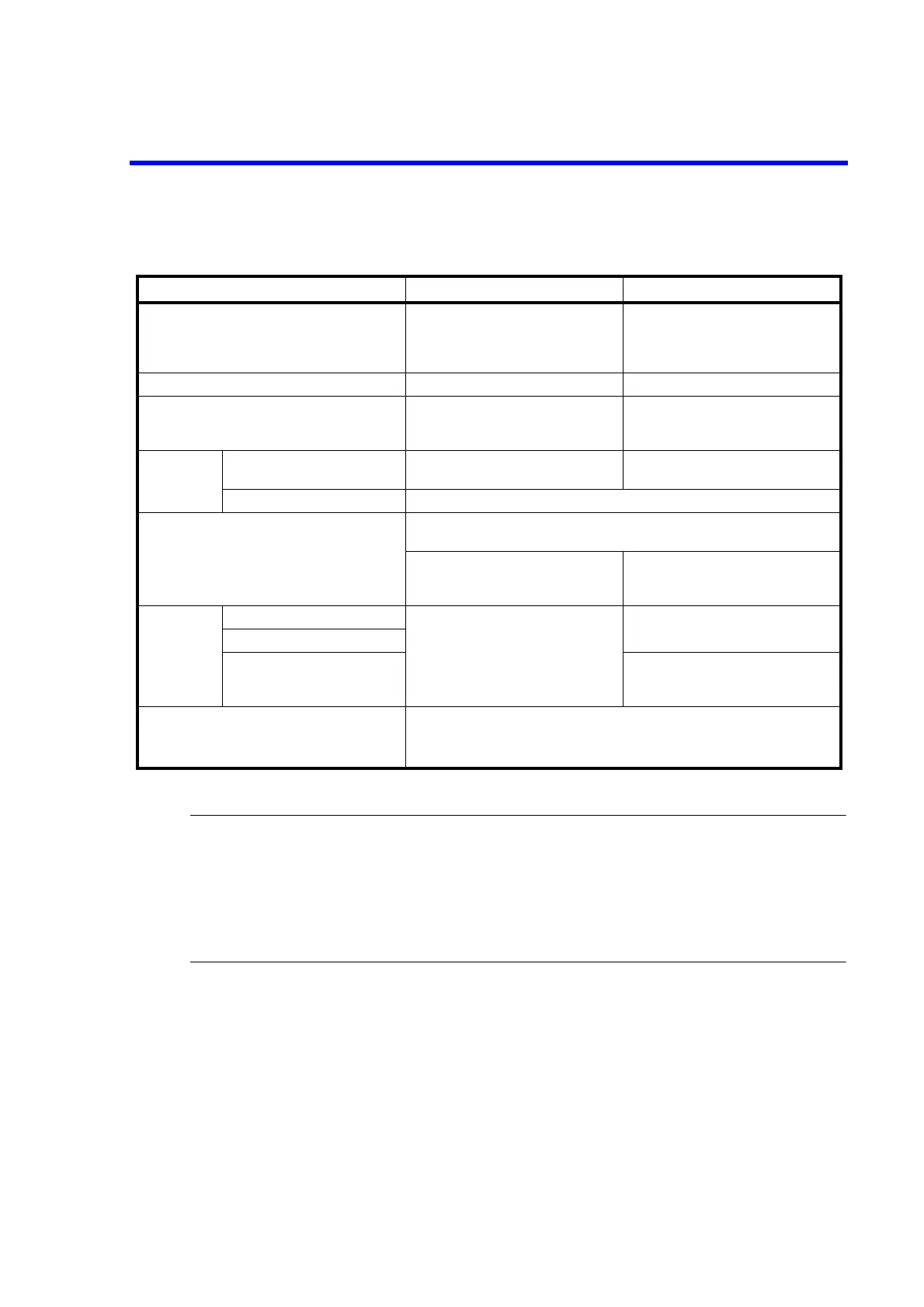
Table 5-18 Comparison of Memory Store Operations
Normal Burst
Recommended usage Normal measurement
When storing measured data for regular
measurement such as DC or pulse mea-
surement
High-speed measurement
When reading the measured data after
measuring a certain number of times such
as sweep measurement
Minimum repeat time (*) 10 ms 2 ms
Measurement data display Displayed in real time Displayed in idle time of measurement
tasks, or when measurement is not per-
formed.
Data output Reads the latest data by the
ENTER key.
Available Not available
RECALL and RN1 commands Available
Operation at memory full The ST indicator blinks.
MFL (bit 10) of the device event status register is set.
Storing data is stopped. Measurement stops.
Sweep mode: STOP
DC or pulse mode: HOLD
Comparator
calculation
results
Complete Out HI/GO/LO signal Output in real time No output
Buzzer
HI/LO/GO display Displays in idle time of measurement
tasks, or when measurement is not per-
formed.
Flag for the specified number of memory stored
data reached
This flag bit is set when the number of measured data reaches the specified number of
stored data in the measurement buffer memory (using the RNM command).
Device Event Status Register ASM (bit 4)
(*) Integration time: 100 s. Source delay: 30 s. Measurement delay: 100 s.

 Loading...

