3-6 Chapter 3
Adjustments and Correction Constants
A9 Switch Positions
A9 Switch Positions
1. Remove the power line cord from the analyzer.
2. Set the analyzer on its side.
3. Remove the two lower-rear corner bumpers from the bottom of the instrument with the
T-10 TORX screwdriver.
4. Loosen the captive screw on the bottom cover’s back edge, using a T-15 TORX
screwdriver.
5. Slide the cover toward the rear of the instrument.
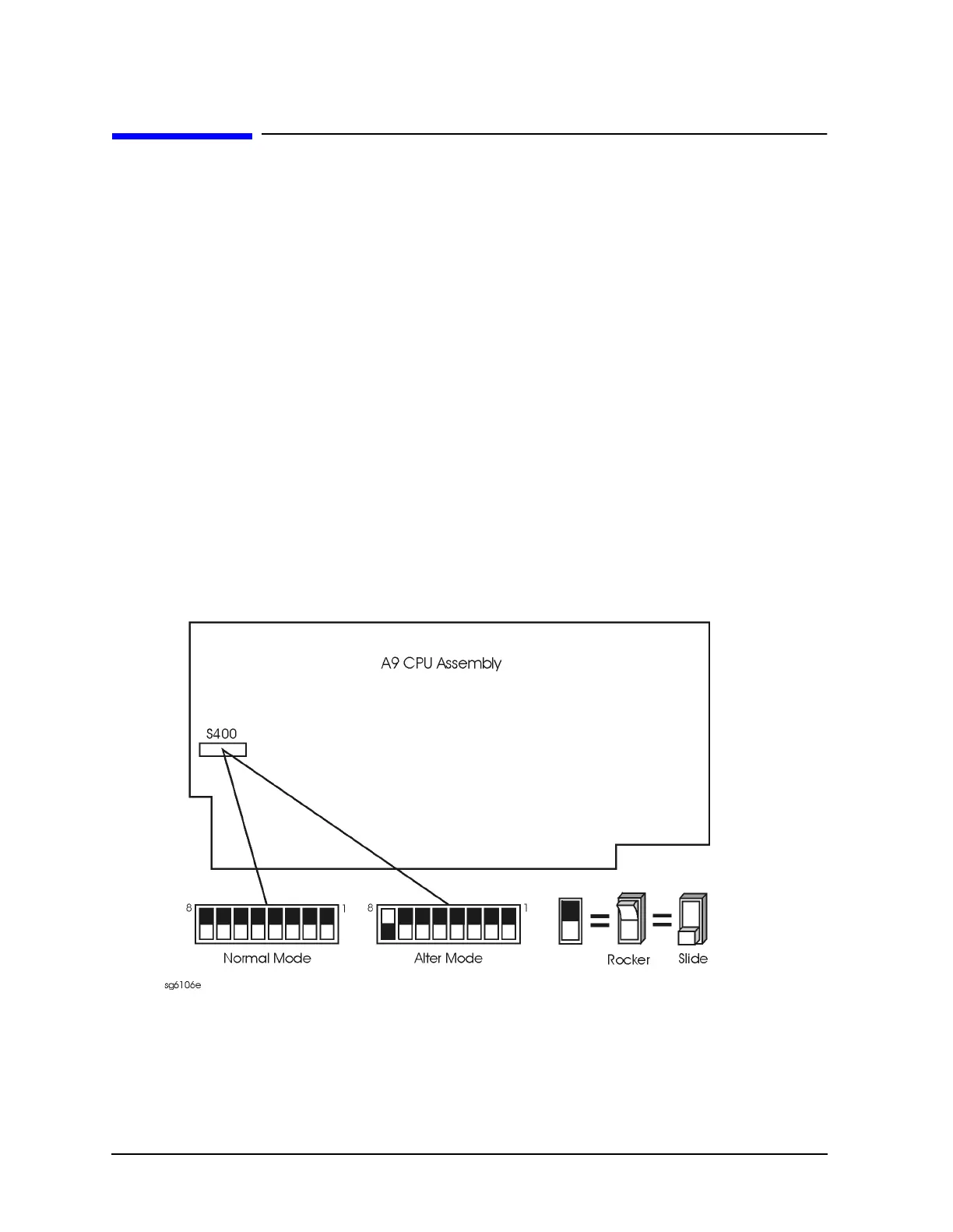
6. Move the switch as shown in Figure 3-1:
• Move the A9 switch to the Alter position before you run any of the correction
constant adjustment routines. This is the position for altering the analyzer's
correction constants.
• Move the A9 switch to the Normal position, after you have run correction constant
adjustment routines. This is the position for normal operating conditions.
7. Reinstall the bottom cover, but not the rear bumpers.
Figure 3-1 A9 Correction Constants Switch
8. Reconnect the power line cord and switch on the instrument.

 Loading...


