Chapter 9 9-5
Accessories Troubleshooting
Inspect the Error Terms
Inspect the Error Terms
Error terms are a measure of a “system”: a network analyzer, calibration kit, and any
cables used. As required, refer to Chapter 11 , “Error Terms,” for the following:
• The specific measurement calibration procedure used to generate the error terms.
• The routines required to extract error terms from the instrument.
• Typical error term data.
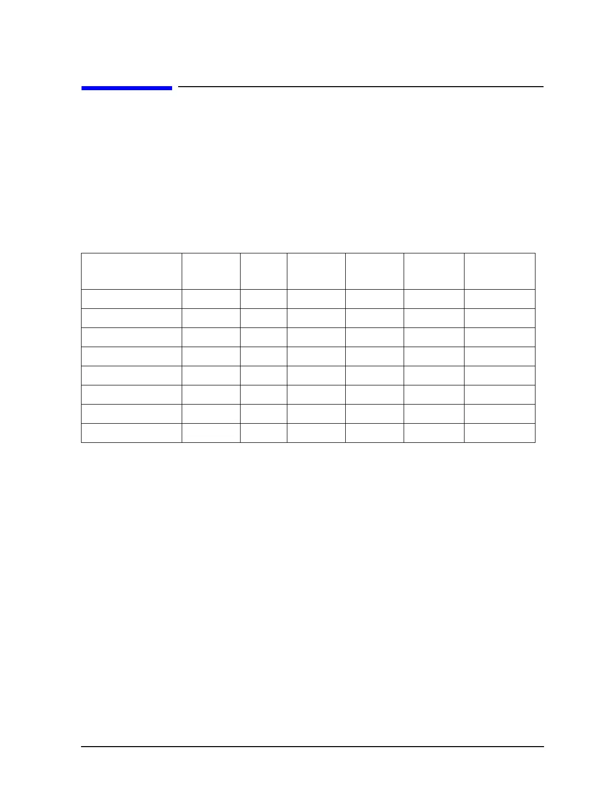
Use Table 9-1 to cross-reference error term data to system faults.
If you detect problems using error term analysis, use the following approach to isolate the
fault:
1. Check the cable by examining the load match and transmission tracking terms. If those
terms are incorrect, go to “Cable Test” on page 9-6.
2. Verify the calibration kit devices:
• Loads (for 8753ES): If the directivity error term looks good, the load and the test port
are good. If directivity looks bad, connect the same load on the other test port and
measure its directivity. If the second port looks bad, as if the problem had shifted
with the load, replace the load. If the second port looks good, as if the load had not
been the problem, troubleshoot the first port.
• Loads (for 8753ET): If the directivity error term looks good, the load and the test port
are good. If directivity looks bad, connect a known good load to the Reflection port
and measure its directivity. If the directivity now looks good, replace the original
load. If the directivity still looks bad, troubleshoot the Reflection port.
• Shorts and opens: If the source match and reflection tracking terms look good, the
shorts and the opens are good. If these terms look bad while the rest of the terms
look good, proceed to “Verify Shorts and Opens” on page 9-6.
Table 9-1 Components Related to Specific Error Terms
Component Directivity Source
Match
Reflection
Tracking
Isolation Load
Match
Transmission
Tracking
Calibration Kit
load X
open/short X X
Analyzer
sampler X X X
A10 digital IF X
test port connectors X X X X X X
External cables XX

 Loading...


