Chapter 4 4-17
Start Troubleshooting Here
Receiver (8753ES)
Receiver (8753ES)
Observe the A and B Input Traces
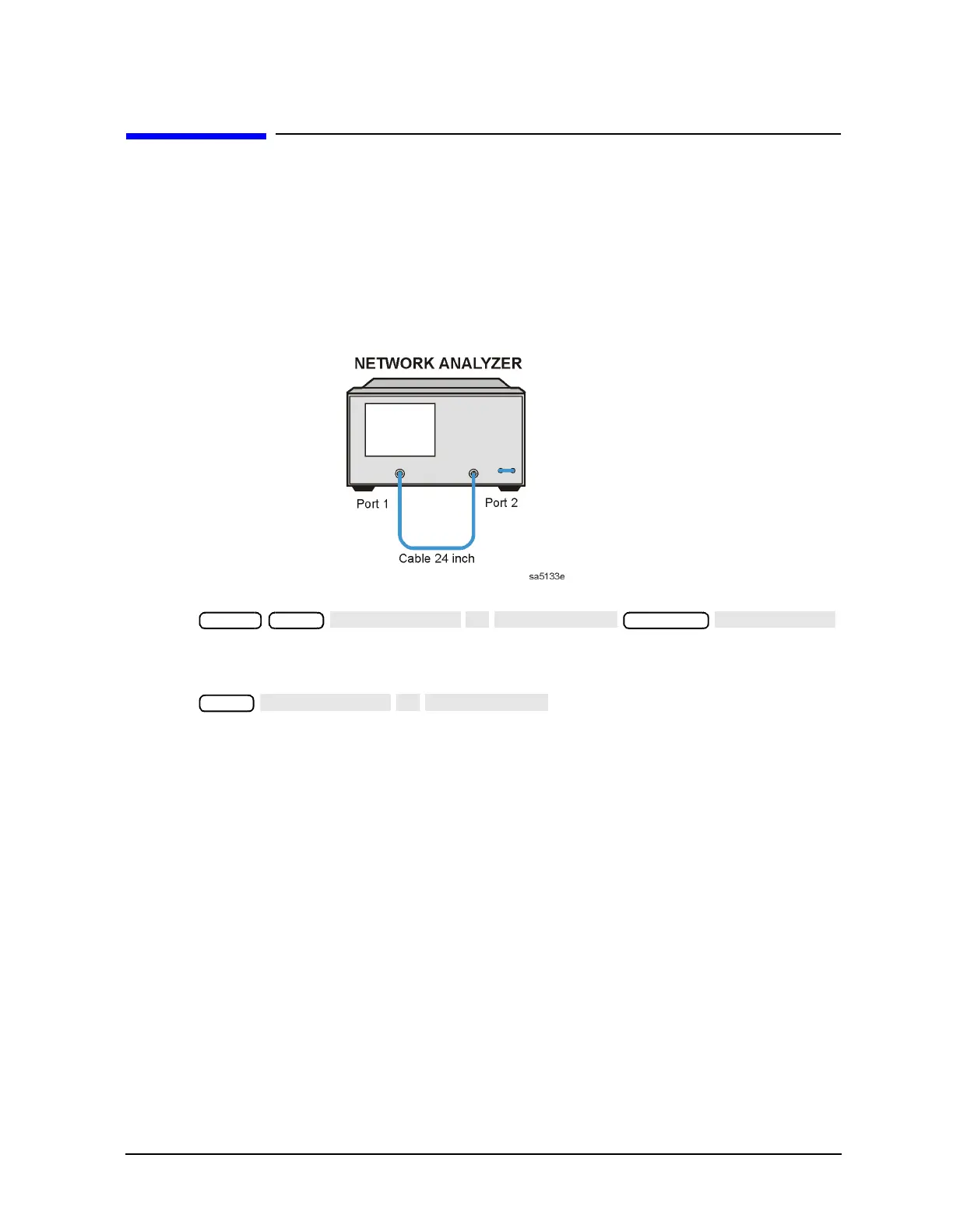
1. Connect the equipment as shown in Figure 4-7. Be sure that any special accessories,
such as limiters, have been disconnected. (The through cable is part number 8120-4779
for 50Ω analyzers and 8120-2408 for 75Ω analyzers.)
Figure 4-7 Equipment Setup
2. Press .
3. Observe the measurement trace displayed by the A input. The trace should have about
the same flatness as the trace in Figure 4-8.
4. Press .
5. Observe the measurement trace displayed by the B input. The trace should have about
the same flatness as the trace in Figure 4-8.
Preset Meas
Scale Ref
Meas

 Loading...


