Chapter 3 3-19
Adjustments and Correction Constants
Sampler Magnitude and Phase Correction Constants (Test 53)
8. Press . Make a
note of the insertion loss (found in the upper-right corner of the analyzer display).
Proceed to “Sampler Correction Constants Routine” on page 3-20.
Determine the Insertion Loss of the Cable at 1 GHz
(8753ET)
1. Press .
2. Press .
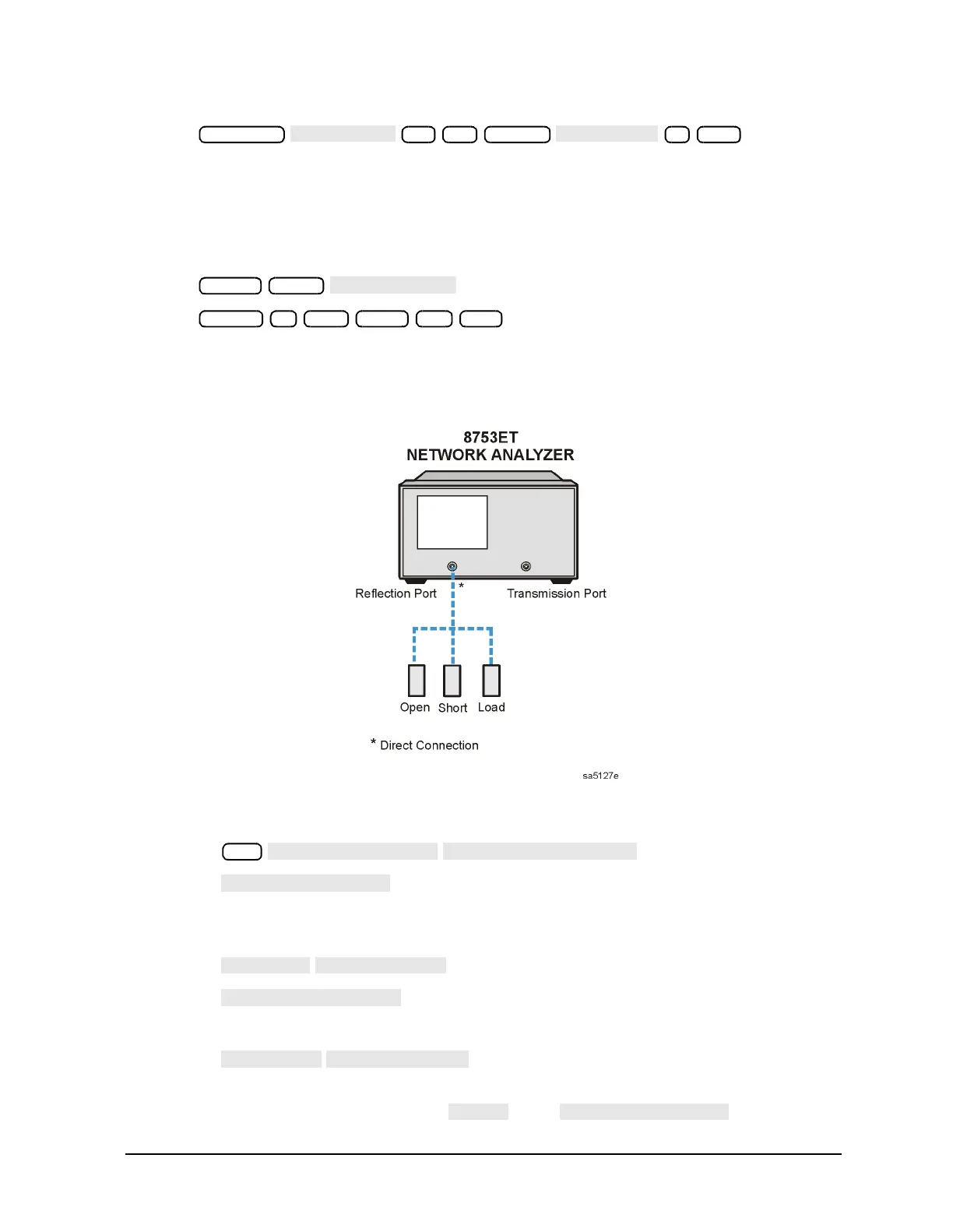
3. Refer to Figure 3-5.
Figure 3-5 First Connection for Insertion Loss Measurement (8753ET)
4. Perform a 1-port calibration by performing the following steps.
a. Press .
b. Press .
c. Connect the open (from the calibration kit) to the Reflection port as shown in Figure
3-5.
d. Press .
e. Press .
f. Connect the short to the Reflection port as shown in Figure 3-5.
g. Press .
h. Remove the short from the Reflection port, then connect the load to the Reflection
port as shown in Figure 3-5. Press , then .
Scale Ref
.1
Marker
1 G/n
Preset Meas
Center 1 G/n Span 50 M/µ
Cal

 Loading...


