Chapter 2 2-45
System Verification and Performance Tests
Agilent 8753ES System Verification and Performance Tests
8. Test Port Crosstalk
Perform this test to measure the maximum level of signal leakage between the analyzer’s
test ports. Crosstalk is measured with shorts attached to the test ports after a
normalization measurement with a thru.
Analyzer warm-up time: 30 minutes
Specifications
Required Equipment
Procedure
Normalization from 300 kHz to 3 GHz
1. Connect the 24-inch cable between the analyzer’s test ports 1 and 2 as shown in
Figure 2-26. Use the appropriate cable for your analyzer (50Ω or 75Ω).
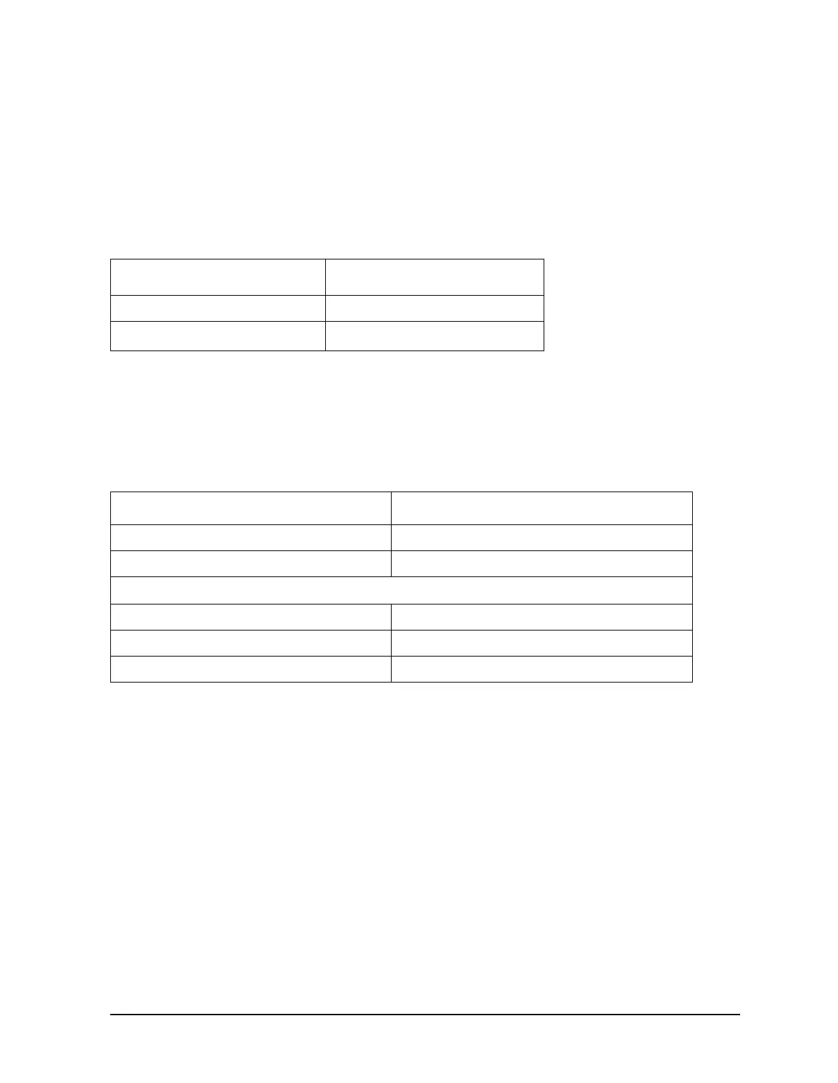
Frequency Range
Crosstalk
a
a. Measurement conditions:
25 °C ±5 °C; normalized to a through; measured with two shorts
(or shielded open); 10 Hz IF BW; averaging factor 8;
alternate mode; source power at +10 dBm (or +8 dBm for
Option 014 or Option 075).
300 kHz to 3 GHz < −100 dB
3 GHz to 6 GHz
b
b. Only for analyzers with Option 006.
< −90 dB
Description HP/Agilent Part or Model Number
Calibration Kit: 7-mm 85031B
Cable: APC-7, 24-inch 8120-4779
Additional Equipment for 75Ω Analyzers
Calibration Kit: 75Ω, Type-N 85036B
Cable: 75Ω, Type-N, 24 inch 8120-2408
Adapter: 75Ω, Type-N (m) to Type-N (m) part of 85036B

 Loading...


