Chapter 12 12-15
Theory of Operation
Source Theory Overview
A3 Source
This assembly includes a 3.0 to 6.8 GHz YIG oscillator and a 3.8 GHz cavity oscillator. The
outputs of these oscillators are mixed to produce the RF output signal. In Option 006
(30 kHz to 6 GHz) the frequencies 3.0 to 6.0 GHz are no longer a mixed product, but are
the direct output of the YIG oscillator. The signal tracks the stable output of the
synthesizer. The ALC (automatic leveling control) circuitry is also in the A3 assembly.
Source Super Low Band Operation
The Super Low Band Frequency Range is 10 kHz to 300 kHz. These frequencies are
generated by the A12 Reference Board. They are the amplified output of the fractional-N
synthesizer. This output is not phase locked and is not subject to ALC control. Refer to
Table 12-1.
Source Low Band Operation
The low band frequency range is 300 kHz to 16 MHz. These frequencies are generated by
locking the A3 source to a reference signal. The reference signal is synthesized by mixing
down the fundamental output of the fractional-N VCO with a 40 MHz crystal reference
signal. Low band operation differs from high band in these respects: The reference
frequency for the A11 phase lock is not a fixed 1 MHz signal, but varies with the frequency
of the fractional-N VCO signal. The sampler diodes are biased on to pass the signal
through to the mixer. The 1st IF signal from the A4 sampler is not fixed but is identical to
the source output signal and sweeps with it.
The following steps outline the low band sweep sequence, illustrated in Figure 12-4.
1. A signal (FN LO) is generated by the fractional-N VCO. The VCO in the A14
Fractional-N assembly generates a CW or swept signal that is 40 MHz greater than the
start frequency. The signal is divided down to 100 kHz and phase locked in the A13
assembly, as in high band operation.
2. The fractional-N VCO signal is mixed with 40 MHz to produce a reference
signal. The signal (FN LO) from the Fractional-N VCO goes to the A12 reference
assembly, where it is mixed with the 40 MHz VCXO (voltage controlled crystal
oscillator). The resulting signal is the reference to the phase comparator in the A11
assembly.
3. The A3 source is pretuned. The source output is fed to the A4 sampler. The
pretuned DAC in the A11 phase lock assembly sets the A3 source to a frequency 1 MHz
to 6 MHz above the start frequency. This signal (source output) goes to the A4 R input
sampler/mixer assembly.
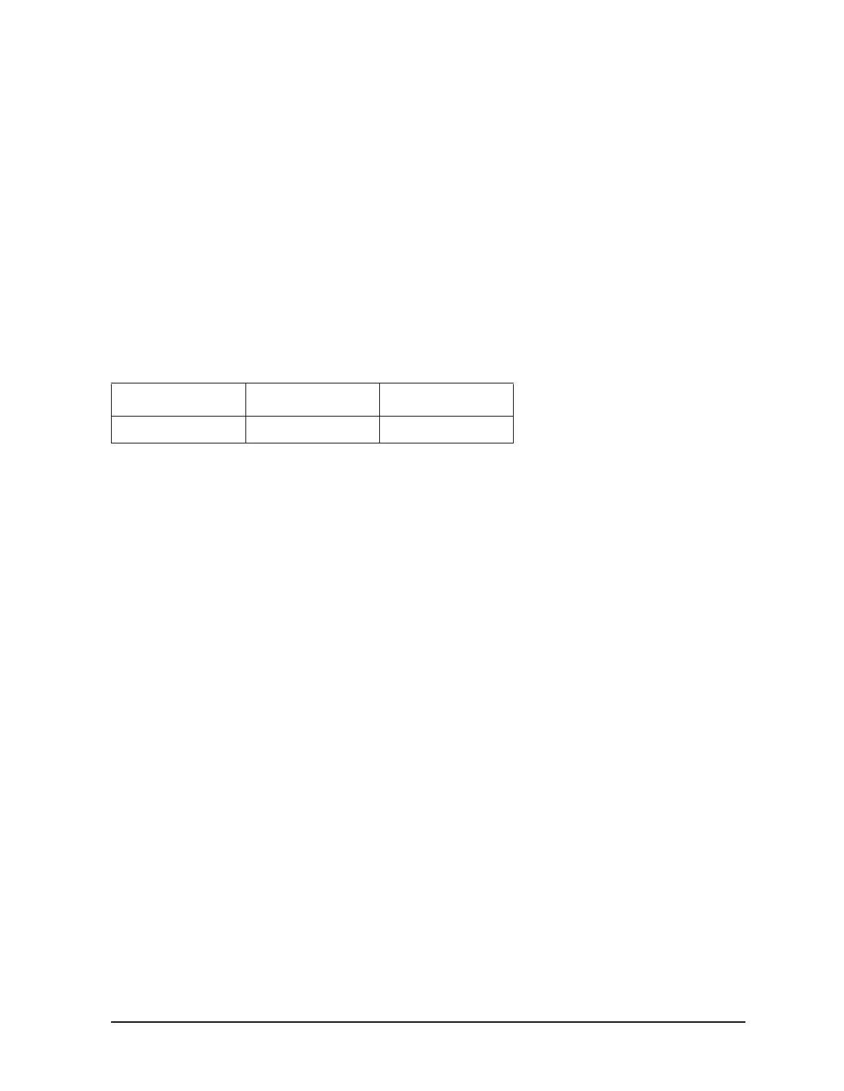
Table 12-1 Super Low Band Subsweep Frequencies
Fractional-N 1st IF RF Output
40.0 to 43.3 MHz 0.010 to 0.300 MHz 0.010 to 0.300 MHz

 Loading...


